RA-40 Audio Level Adjustments
[This procedure is for the Yaesu DR-1X Fusion repeaters only] David Lowrance AL5X
Calibration Procedure - RA-40 - Audio Levels
With an FM modulation transmitter, frequency deviation is a function of audio level at the modulator stage.
FM output frequency is determined by multiplying a base carrier
frequency which we modulate with the audio, and when we then raise the
frequency using multipliers the deviation also raises with it.
Thus the actual audio levels into the transmitter will have to decrease as the frequency of the transmitter increases.
Example: If you adjust the repeater on 444 mhz for a correct level
about 9db down from maximum input to the repeater audio stage, if you
change the frequency to 146 mhz you will have to raise the input level
by 3x.
444 / 146 = 3.041
A level as used below will come out right for the 444.000 repeater, but
it will be 3 times too low for the 146.820 repeater to match the sound
level on a remote radio using the repeater.
As if the level is too low, then at the receiving radio using the
repeater, the volume will have to be raised. At the squelch delay on
the end of the transmission, the noise level may break in very loud
before the courtesy tone.
This means that if you are calibrating multiple RA-40 boards, you must
keep track of which repeater they will be going into and adjust
accordingly for the band being used.
As we first set the voltage levels of the repeater input and output
using the analog adjustment, and then add the loss using the Pi /3
software, the final software setting is easy to change if we get it
drastically wrong.
Keep this in mind as you read through the calibration process.
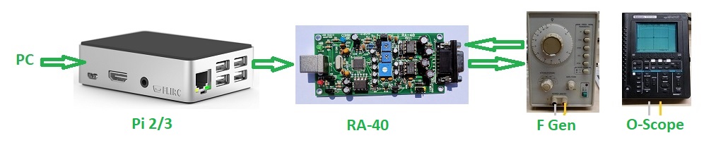
The RA-40 board can be calibrated
for the specified DR-1X repeater levels by connecting it to the Pi 2/3, then setting up
the test gear shown above.
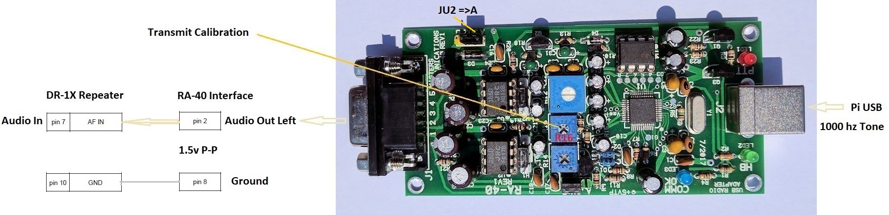
Transmit Calibration:
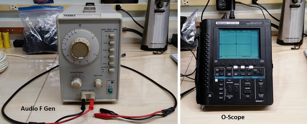
For the Transmit Adjustments, the Audio Generator is used only for a 600 ohm termination, leave the power off.
Verify this using an ohm meter. Not all the output levels may be exact. Find the best one closet to 600 ohms.
The scope is then used with it to read the Peak To Peak level of the test tone from the Pi.

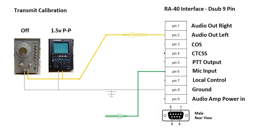
Calibration Plug:
Make up the 9 pin male plug with the three wires connected to the pins in the diagram above.
Connect the F gen and scope in parallel as shown in the diagram, pin 8 ground [white], and pin 2 Audio Left Out [Yellow].
Initial Hardware Setup:
See the photo below.
Set jumper JU2 Audio Power to position A for +5 volts.
Set Potentiometer R16 clockwise to 1/4 from the bottom position. It is the center Potentiometer.
The shaft is marked in 1/4 turns with a white dot on one corner.
Install the Pi /3 software:
Log into the Pi 2/3 with Allstar software installed: user: root password: you set up during Asterisk Allstar installation.
I use PUTTY on my windows10 PC and access the Pi over my local network with a fixed IP address.
Set up parameters and tone output level:
From the main menu hit the down arrow key to highlight [12 run simpleusb-tune-menu Application] now hit enter.
In the menu type E [test tone keying] hit return, Ensure the E line now says (currently enabled)
In the Pi 2/3 software type 3 [Set transmit A level] and set it to 999. This is the maximum level the Pi can produce.
Analog Adjustment:
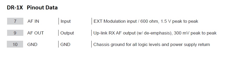
After you hit return it will tone out for 5 seconds and you should be able to read the peak to peak voltage on the scope, at 1.5 v P-P and freeze frame it on the scope if you can.
You can repeat the last step typing the same number to then adjust R16 until the level on the
scope is 1.5 v P-P, maximum input level to the repeater on transmit.
[Alternately you can use the D function to send the tone as a few
pulses but the duration is shorter and much harder to read on the scope.]
When the level is accurate go to the next step.
Software Loss Setting:
Type 3 [Set transmit A level] and set it to 125 approximately 9 db loss below maximum, if you will be using a frequency in the 440 mhz band.
For frequencies in the 2 meter band, set this value to 375, approximately 3 times higher.
This setting should closely match the DR-1X spec, giving a dynamic
range of volume before it starts compressing the tops of the audio
levels.
Save Settings:
Type w[save current parameters] hit enter.
Read the screen and make sure the parameters were actually saved before shutting down the power to the Pi.
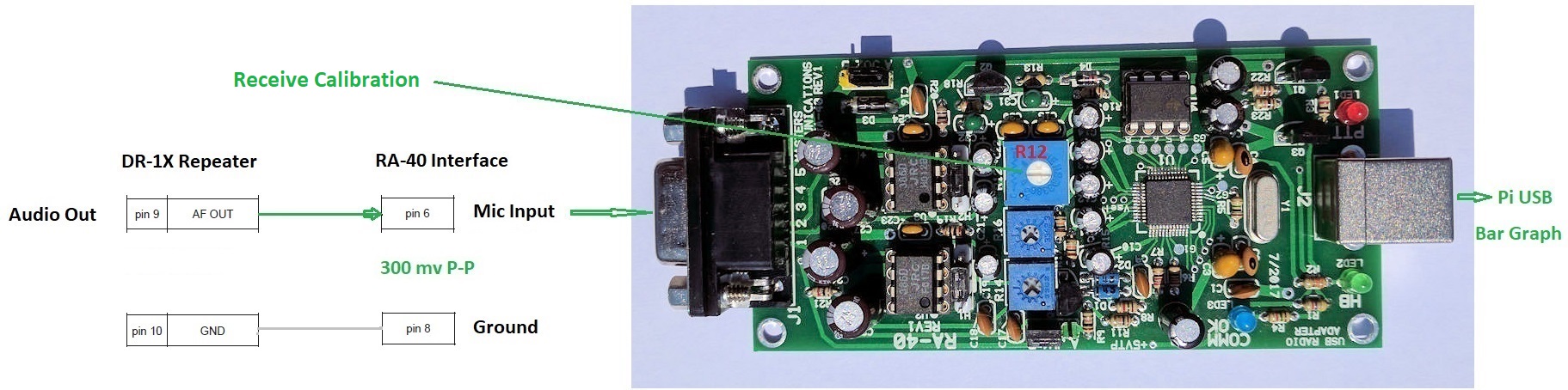
Receive Calibration:
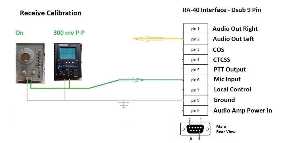
Hardware Setup:
Set up the audio signal generator between pin 6 Mic Input [Green] and Pin 8
ground [White].
Using the scope to monitor this, set the frequency to 1000 hz, and set the level to 300 mv P-P.
Set Potentiometer R12 to a 1/4 from bottom position. It is the largest Potentiometer.
Software Setup:
In the Pi software type B [Toggle RX Boost Mode] we want this on. Ensure the entry menu now indicates (RXboost enabled)
Type in P enter at any time to check the states and values of the settings.
In order to read and adjust the level, you will have to key COS using the Pi software.
Type K [manually key COS] hit enter.
Adjustments:
Type 2 [set RX voice level]
There are V --- 3K and V --- 5K positions on the Bar
Graph.
You want to adjust R12 volume level to land right under the point
of the V for the USB digital input level you desire.
Enter a value of 500, type 500 hit enter.
Adjust potentiometer R12 for a reading on the bar graph of V --- 5k.
The voice level "should" now be almost identical through the repeater whether the RA-40 controller is on or off.
Save Settings:
Type w [save current parameters]
Read the screen and make sure the parameters were actually saved before shutting down the power to the Pi.
End Calibration Procedure
USB Drivers
If the analog adjustments are done as shown above, you should not have
to ever touch them again. Any further adjustments can be done in the pi
software.
We did the first analog adjustments using the stock USB driver that is
accessed through the main menu on initial setup of the software package. [simple-usb.conf]
Later we decided we wanted more features on our repeaters, and then we updated to the more advanced USB driver that allows for automatic software adjustment of tone levels also, for 2 way tones. [usbradio.conf]
I believe it also gave some more control over squelch. This
is found inside the Allstar package already, the menu can be
modified to point there instead of the stock USB driver, and the load
file can be modified to boot it properly.
Stock driver - simple-usb.conf
Advanced driver - usbradio.conf
"The only real trick was to edit the menu to call the right program for configuration." KL4EL
References
Calibration Verification
With a background in Telephony and years of setting levels on carriers,
I had wanted a more exact way to ensure end to end accuracy.
However after doing initial set up and level adjustments, the project
below was never completed. We became pretty satisfied with the results
after the second USB driver was added with it's auto setup ability.
The assumption that if we do not exceed the maximum levels into the repeater all is good, does seem to work in this case. And in the case where you do exceed a level the DR-1X will compress or limit it anyway.
If it compresses the audio from overdriving it, then it will loose a
bit of the audio dynamic response and may sound a little muddled, I have never seen it splatter into adjacent channels.
If you hear it muddled then you turn it down in software, no problem.
For those who need absolute end to end testing I left the section
below, as untested.
It is aimed more at what a commercial tech would have been doing in
years back before these kind of self limiting circuits were being
added.
Adjusting it by ear is thus a pretty safe process in reality, which was hard for me to believe going in.
Out of band distortions can be generated in the repeater if we do not get our audio levels correct, as it is an FM transmitter.
Thus before this procedure can be fully certified, we will need a way to
verify the levels will not be distorting due to over modulation.
The following must be done to ensure our tweaks in the above procedure were accurate.

Two Baofengs, or any other VHF UHF amateur radios, can be used for this procedure.
Program both Radios for the repeaters frequencies.
The basic concept is to test the audio levels through
the repeater with the RA-40 controller up, then do it with the
controller power turned off, and compare the audio quality and level.
If you did the stock alignment above, it should sound "close" to identical both ways.
If the level is radically different or distorted, we will need to determine how
far off it is, and likely adjust the transmit level on the RA-40 down to
compensate.
For this we may even need to set up the tone generator into the XMT
Radio, then adjust the level while watching the bar graph for
a full scale deflection.
Another test cord will be in order to monitor the 3 pins with the cord plugged into the RA-40 and the DR-1X repeater.
Also an Echolink connection may be necessary to resolve which
adjustment to compensate with if these levels are found to be incorrect.
This is a concern if you are going to be interfacing with the Internet for Echolink or Allstar functions.
Baofeng BF-F8HP Connections
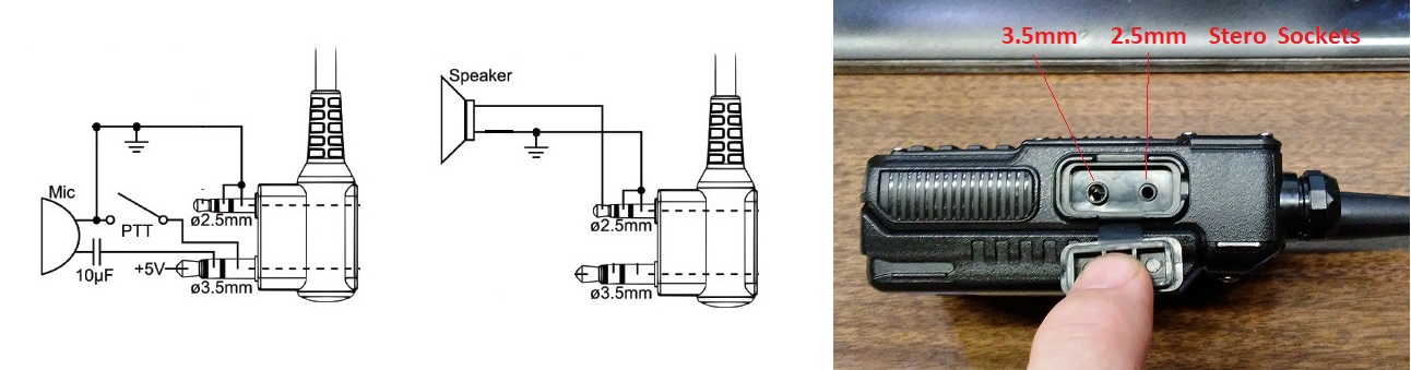
The Transmit radio side will require both the 3.5mm and the 2.5mm cords
be used to wire in a tone generator with a push to talk toggle switch we can
turn on.
The receive radio will only require the 2.5mm cord to power a meter.
Remember to turn the radio off when plugging in and removing cords,
there is +5v on the tip of the 3.5mm jack.
Parts

The Sockets can be mounted into a small project box. The speaker is
simulated using an 8 ohm resister. A toggle is mounted for the PTT
function and the Test jacks connected accordingly for the tone input
and meter output.