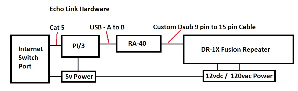
Yaesu DR-1X Fusion Repeater Project with a Pi 3 and RA-40 Control Interface Board

The Yaesu DR-1X is a solid repeater system. Used for FM mode it is a
bit lacking in control features, not even providing a courtesy tone.
In order to interface with the Echo Link system over the Internet, and
also to use special features with DTMF tone selection, an external
controller must be added.
The RA-40 interface board was chosen and a Pi /3 computer as a
best cost effective method, with a feature rich package already
available.
Software Comments
Allstar [Asterisk] software was installed on the PI 3. It was discovered to be the most advanced package, and user friendly.
Within it is the correct control package to operate the PTT function through the RA-40 control board interface on pin 13.
The package offers Echolink, and Allstar directly with a Linux OS from
one download for the PI 2/3 [4 GB micro SD]
See references section below, for the software downloads.
I also have a Linux guru KL4EL to assist manipulating the PI software
package which was originally a system that ran a telephone PBX, as I
understand.
I then run backups of the micro SD cards using a windows 10 machine with Win32DiskImager.
You can use larger micro SD's, and I started out using 8 GB then moved
to 32 GB, but as it turns out this only makes my backups much larger
and takes longer to copy them.
Engineering Section - Hardware and Cabling
RA-40 Repeater Control Interface Board
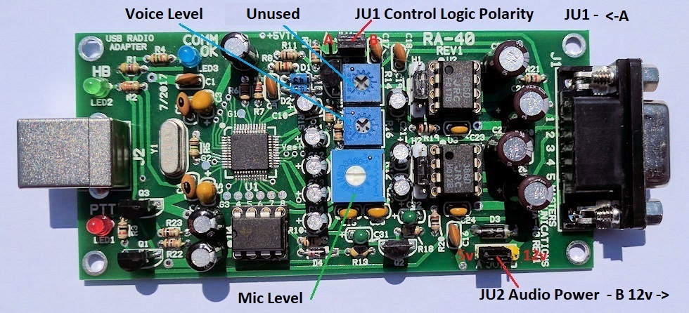
LEDs
Green HB = Heartbeat indicates PI/3 is talking to the RA-40 control board
Blue Com OK = Heartbeat Timer Pi is Up
Red PTT = Push to Talk indicates Repeater is transmitting
Potentiometers
Voice Level = Left audio channel USB => Transmit audio to Repeater from Pi/3
Mic Level = Audio input to USB <= Receive Audio from Repeater to Pi/3
Option Pins
JU1 Local / Remote
Mode Polarity Hi = Remote mode [set to B] after
doing RA-40 modification [green boards only].
JU2 5v to 12v Audio Power amp Selection Set to 12v [set to B]
[See References Section below for ordering this board]
RA-40 Circuit Diagram [with DR-1X modification shown]

It was discovered that if the Pi/3 and RA-40 loose power, the system
does not release back to local control.
The DR-1X local control lead needs to see an opened circuit, rather then 5v, or ground when the DC power goes to zero.
One 2n2222 transistor and one 4.7k resistor were added for an "opened collector" circuit. JU1 was
set to B because the signal on pin 7 is now inverted.
When the power is removed from the Pi/3, the repeater goes back into
local mode, dropping out of remote mode, and continues to work, without
the courtesy tones or other features the controller adds.
Also
when the Pi is rebooted or locks up the repeater will maintain local mode until the
Pi/3 comes up and the blue Com OK light goes to "steady on" after which
it will switch to remote mode.
Whenever the blue light is out,
indicating the USB port is down, the repeater switches back to local
mode.
The added transistor will have 3.4 vdc on the collector from the
repeater pin 1, and will have to sink 68 micro amps to pull the lead
low.
The 2n2222 transistor will switch with base resistor values between 1k and 1 meg.
A BC547A transistor can also be used as in the photos below and resistors in that range. A 2.2k was used in the first mod.
I have had the modified circuit in service now for several days, and it appears to be working fine.
When I switch off the power to the Pi, local mode is instant. After the
Pi reboots it switches back instantly also. [1 - 21 - 2018]
A new board that will be red in color is being designed to add this modification.
Modification Details

The foil on pin 7 is etched opened near the 9 pin connector.
Note the two small foil holes on either side of pin 8. Watch for solder bridges when the transistor is soldered to pins 7 and 8.
Both holes are ground, so if pin 7 is bridged the repeater will not switch modes.
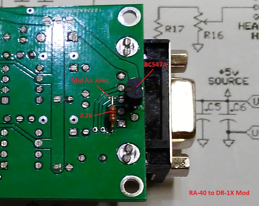
Emitter is bent outwards and shortened to keep the transistor close to the bottom side of the board, then soldered to pin 8.
Collector is bent the opposite way outwards and soldered to pin 7 of the 9 pin connector foils.
The 2.2k resistor is stuck through the hole and soldered, then bent
over to meet the base of the BC547 transistor and soldered in mid air.
The ends are then clipped off.
Because I mounted the board on standoffs, there is enough clearance under the board to keep the transistor up off the shelf.
This modification of the RA-40 board resolves a long standing problem
with reliability and I am glad we took the time to come up with
this solution.
AL5X 7-19-2018
Custom Cable 9 pin Dsub on RA-40 to HD15 pin Control Port on DR-1X Repeater
This cable uses 8 conductor shielded wire. One each 9 pin D-sub male and one each HD15 male 15
pin 3 row VGA style D-sub.
The same enclosure hoods are used for both connectors.

I opted for the solder tail connectors.
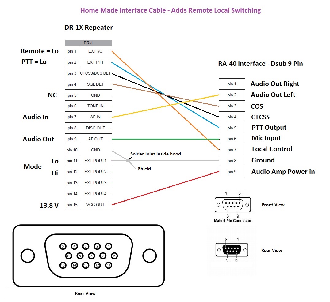
Note: The shield should be connected to pin 10 on the HD15
repeater port side and left opened on the RA-40 9pin side. I
accomplished this with a solder joint of all three wires above the
connector but inside the hood. Pins 10,11,and shield.
Note: For Remote / Local switching to work properly, see the modification above on the RA-40 circuit.
Note: It was discovered that pin 5 on the DR-1X was not connected
inside the repeater and could not be used as the ground on the cable to
the RA-40 board pin 10 had to be used.
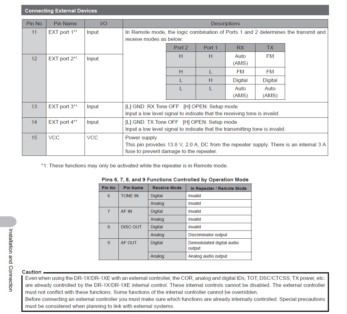
Note: Pin 11 is also grounded on the repeater controller port to force
the repeater into Analog FM mode when the controller goes active.
DR-1X Repeater Pinout
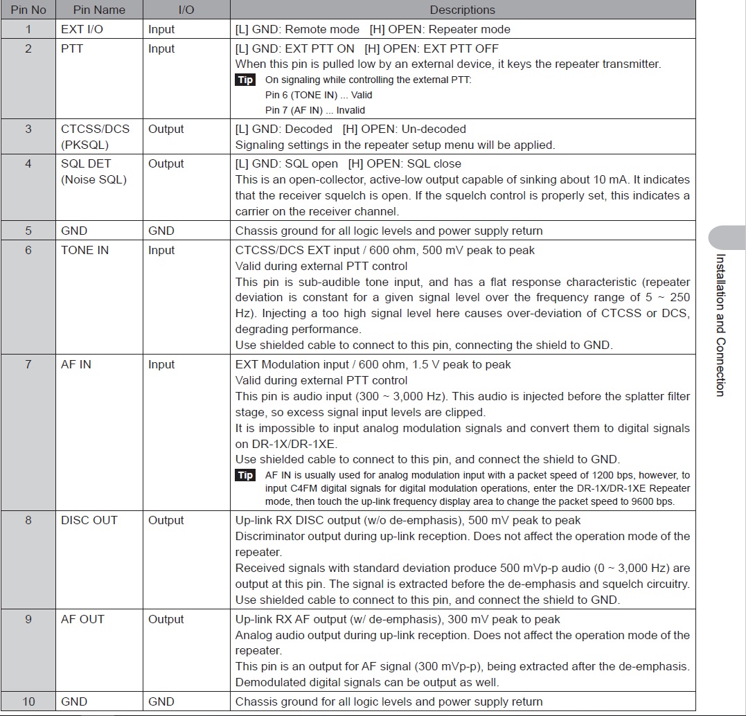
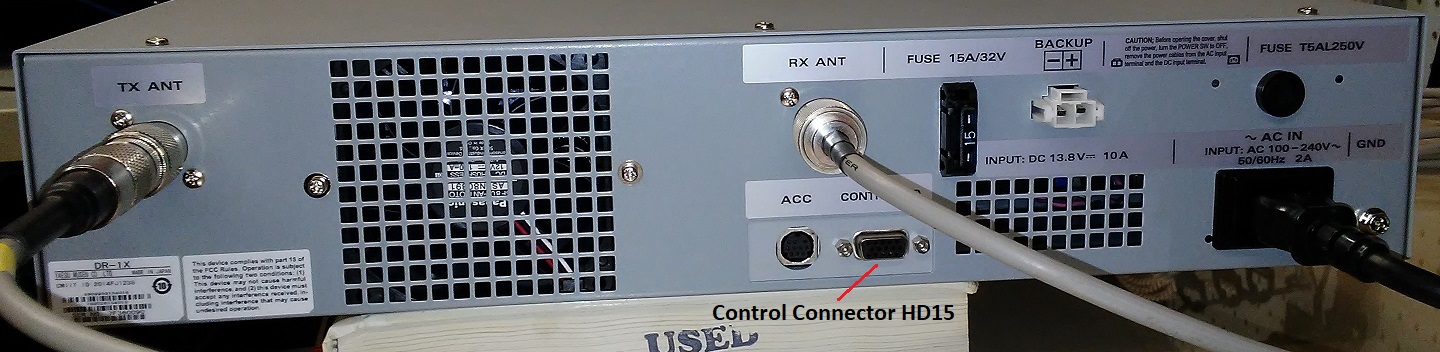
The ACC jack is used only for firmware upgrades. All remote control functions are done through the 15 pin Control I/O Port.
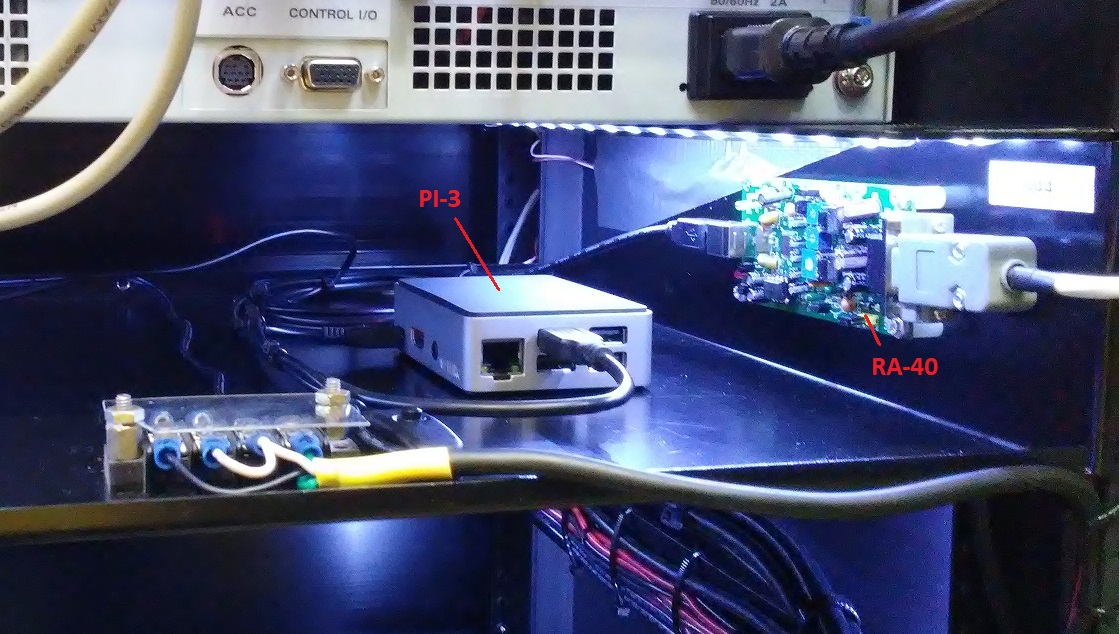
Cabinet Photos

DC Power Distribution and Battery Backup
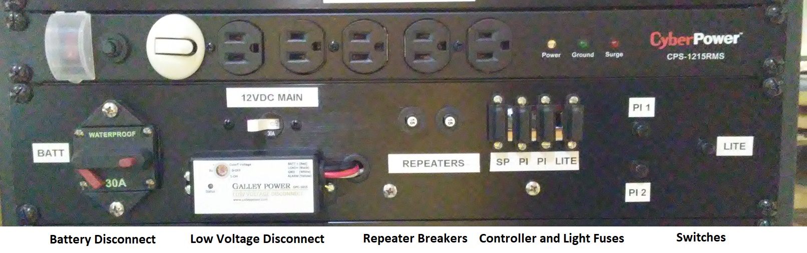
The DC power distribution panel was custom made to handle a standby
battery box with low voltage cutoff, a DC power supply, and some
control switches, including the 2 Pi/3's and the internal light LED
strips for working inside the cabinet.
Original Design Print

Note the Sealed Automotive Fuses used inside the insulated
automotive battery box as a safety feature. Nothing worse then shorting
out battery leads with no protection.
Then right up front on the panel is a battery disconnect switch /
breaker between the rectifier and the battery, then finally the load
disconnect breaker switch protecting the low voltage cut off unit.
The cabinet should never draw over 25 amps total, with both repeaters transmitting and all the other loads turned on.
References:
RA-40 Supplier
[I do not recommend the cables they recommend for the DR-1X repeater, as they strap the DR-1X permanently into remote mode.
To switch back to local mode you must pull the control cable off the back of the repeater.
With the RA-40 modification detailed in this document above you can simply turn the power off to the Pi.]
Pi 2/3 Software
They recommend at least a 4 G byte micro SD chip for the Pi. We have
been using both 8 and 32 Gig chips successfully in our Pi /3's.
Once loaded they can only be copied to identical size chips, if you want backups of the software for each repeater.
If I did it again I would use all 8 Gig chips, they are cheaper and still lots of extra room.
You may spend some hours setting up each repeater build, so this is an important consideration.
Software will require obtaining an Allstar node number and an account.
Normally the Trustee of the repeaters by the club will have to do this
one.
Numbers below 2000 can be used locally, over 2000 will be assigned by
the world wide area network group when you establish your account.
If you operate two repeaters on the same local Internet box subnet, you
can assign the second one yourself below 2000, and they can be linked
together via the local network,
however only one will be accessible from outside if your Router only has one IP address on the Internet.
Echolink will also require a unique node number be assigned in your software, granted by the Echolink account process.
Both will require a valid Repeater Call Sign with the FCC, and there is a waiting time involved after account setup.
You must first obtain the Allstar node number to bring up the software, before Echolink can be activated using it's node number.
Pi / 3 programming was done by Todd Dokey KL4EL
Software Support
Yaesu DR-1X
Yaesu DR-1X
Note this document is only for the DR-1X, the DR-2X does not have the same control port.
Document preparation and site Admin - David Lowrance AL5X