Magnetic Resonance
2020 - 4 - 19 Dave L
This older document, during experimental development of the Vibration
to EM sections of the site, has been updated to reflect better accuracy.
It is intended to introduce the electrical experimenter to new ways of
calculating mass resonance and electrical resonance values so they can
be coupled to powering sources of pure vibration including the earths
fields.
To use the vibration path, which can become self sustaining, to the Electric Field as a source of power.
The power of a "recursive vibration loop" can be shown clearly in
the Joe Cell work, where the propagation of these two fields being very
different, "electrical" and "radiant mass vibration," are clearly shown
to interact.
The Joe Cell work even gives examples of how to tap into a field of energy from the earth using correct frequency methods. Caliper Injection from the Background Field
As well as Starting up a field in the cell that stays active after the
DC power is totally removed from the Cell, and will expand
geometrically to fill a room, or a car. Secrets To Instant Charging of a Joe Cell
It is highly recommended, the electrical engineer first read through the
first several documents in the Joe Cell section for a better understanding of
the two kinds of energy we can use and how they each interact but are routed in different ways.
Joe Cell Menu
2019 - 4 - 24
Understanding Electrical "A" field resonance, and Volumetric Quantum Resonance.
It is assumed you have some previous knowledge of AC resonance in conventional electronics theory.

Magnetic Field is a Gradient
Pictured above is a textbook coil with iron core showing the magnetic field lines of flux.
As we were all taught, the field forms into a donut or torus, with the source of energy appearing from inside the iron core,
and then available to interact with other iron , nickel, cobalt,
items at a distance away, which will drop off as the distance cubed in
power from the polar ends of the iron core.
This places the source of the power of the field inside the iron core and/or inside the copper windings.
The external part of the field can be seen as the loading or
entropy side spread outwards under it's own internal repulsion force.
This mental model is impossible to quantify as a volume, as the
geometry of a torus. It will change in intensity with the electrical
current in the coils wire, and the location around the coil of wire.

If we take two paper clips and move around a coil of wire, we will
discover that inside the coil the attraction is stronger near the ends,
and along the outside is very weak along the sides, weaker to the
center.
This will also vary with the wire, some wire has a tin coating, and
some has only enamel coating. Suffice to say the magnetic field is not
uniform in it's power levels anywhere we test it, there is a gradient.
This gradient is not uniform but changes between the polar ends of the field we call North and South poles.
It's field dimensions will change with the material you place into it.
Lines of flux will bend around and distort the field when it interacts
with outside influences with low resistance to magnetic flux.
Suffice to say we cannot calculate the volume of this field as one quantum dimension, it works more as an elastic field and all through it is a changing field density.
The torus model seems to offer little assistance to resonating up
a magnetic field as an equivalent quantum vibration field based on
fractal calculations as we have been using for fixed distance tunning,
as we can do using Joe Cells.
In electrical resonance, the resonance is dealt with as a changing current of
electricity moving into then back out of the coil into a capacitor and
the coils quality called "inductance."
While the capacitor is defined by geometric qualities of plate
dimensions for area, distance between the plates and dielectric
constant of the insulator material between them, the coil is measured
as inductance, or "reaction" to a change of current in real time.
Inductance requires an AC input to measure which is changing in time. It is not a static quality we can label in any other way.
Thus the geometry of a magnetic field is a dampened vibration, naturally generating sine waves that will attenuate over time.
Electrical resonance is Entropic unless we have superconducting wires and lossless capacitors.
There does not appear to be any simple way to use "magnetic fields" to
draw energy from the background field, or the source vibration field,
as we can calculate with vibration fractals, used in other method that
do work.
A Field
 If we make a short coil with a very large diameter, we are able to
observe the qualities of the field inside the copper wire loop, to
discover it does not work in the same way as the magnetic field torus.
The field density of this field does not drop off as distance
squared or distance cubed as do the electric and magnetic fields that
we can measure with our EM test gear, or using two paper clips.
It never ceased to amaze me that we can run an Amprobe through
this loop of wire at any point inside, and get the same reading of
the field intensity.
It does not seem to have a gradient that drops off towards the center no matter how large you make the wire loops.
You can do the two paper clip test anywhere inside this large loop
of wire and there are no location where the field is weaker, then any
other locations.
The magnetic poles of the coil are very close together but seem to
now offer the same power levels to paper clips everywhere inside the
coil, but not outside the coil, where you cannot even get them to pull
together even touching the wire on the outside. The Amprobe must be
connected around the wire and through the center to read the current in
the wire, but it will not work if placed anywhere outside the wire loop.
If we make a short coil with a very large diameter, we are able to
observe the qualities of the field inside the copper wire loop, to
discover it does not work in the same way as the magnetic field torus.
The field density of this field does not drop off as distance
squared or distance cubed as do the electric and magnetic fields that
we can measure with our EM test gear, or using two paper clips.
It never ceased to amaze me that we can run an Amprobe through
this loop of wire at any point inside, and get the same reading of
the field intensity.
It does not seem to have a gradient that drops off towards the center no matter how large you make the wire loops.
You can do the two paper clip test anywhere inside this large loop
of wire and there are no location where the field is weaker, then any
other locations.
The magnetic poles of the coil are very close together but seem to
now offer the same power levels to paper clips everywhere inside the
coil, but not outside the coil, where you cannot even get them to pull
together even touching the wire on the outside. The Amprobe must be
connected around the wire and through the center to read the current in
the wire, but it will not work if placed anywhere outside the wire loop.
The Amprobe may have a very large circular hole, and it will not matter
how you position it around the wire push it in or out the reading will
not change.
The electrostatic charge drops off around the wire at very
short range for low voltages, but the A field has a reach in distance
that seems to be a Quantum effect, having no loss as it moves through
space, similar to light photons.
The men who studied electrical fields and developed our current
understanding called this field the "A" field, and differentiated it
from the Electric and Magnetic fields because they realized it worked
differently.
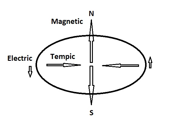
This concept of a quadrature field having not only two kinds of energy
Electric and Magnetic at 90 degrees, but three, all at 90 degrees to
one another.
Wilbert Smith gave us some definitions, from back there in the 50's and
60's, where he opened us to the concept of a third field force that can
also be calculated and modified.

Today we have developed this "mental model" and come up with ways to
measure it's resonance as pure vibration, which can be sensed in the
body and in the pineal area of the human brain.
Mass Vibration Science - Caliper
If you hold a SS caliper near an Amateur radio, you can dial up it's frequency as it transmits and feel this for yourself.
The caliper was the tool of men like Hendershot, a machinist by trade, during that same time frame.
The formula for tunning in the caliper to feel the vibration of the
transmitter in the Radio is [ 1 mm - 1 khz ] and using the volumetric
function to expand this [ 1 cm = 1 Mhz ]
The men who worked around early transmitters could measure the frequency of the coils by feel.
Example: 1430 on your AM radio dial, 1.43 Mhz is 1.43 cm on the
caliper, and you can tune it in and feel it anywhere around the
transmitting tower to miles away.
You simply point the calipers at the direction of the tower and
the SS material vibrates up in your hand. This is a mass vibration
effect and Stainless steel captures it quite well.
The early tech's like Hendershot knew this. That knowledge gave them
ability to create self sustain systems, as Hendershot had successfully
done.
He carefully measured all the critical components of his system which
could power a tube radio of the time, including the gauge
diameter of the wires which have a ratio between them.
The A field, is a quantum field, having no loss and thus can be set up
to self generate using specific ratio functions, which we have been
doing for some years now on Joe Cell tubes.
http://www.resonantfractals.org/Mass%20Vibration%20Science/Machines.html
Joe Cell Applications
It was when experimenters of our time started to notice when they
vibrated up coil cores at specific frequencies, they could begin to
design self running system at small scales.
These do not always work, and we may find the reasons in the other
experiments where we can get consistent results using only Radiant
Vibration fields, that always work.
"A" Field - Area - Volume
The A field can be calculated and
resonated with on two levels. Area, or Volume, as discovered in the
Walter Russell dual cone systems, where we are able to set up standing
vibration fields, and have them couple into the electrical power of a
circuit.
Area = pi * radius^2
Volume = radius^2 * pi * length of the coil winding.
As a coil system, the volume is a quantum unit. The electric field acting on the tempic field. [Wilbert Smith]
Walter Russell Cones Addendum 2
The "A" field is an off balanced Vibration Field
The fact that this field can reach through the mass of an iron
core
creating magnetic flux all the way through it, and electric field
would stop and flow around on the surface, means this field is vibrational in nature. This can be shown in a DC circuit where suposedly there is no frequency changing.
Scalar canceling waves in space will penetrate directly through
any material, and deliver vibration to an entire volume of space or
material. The nature of these waves can be studied in the Scalar Coil
section.
Fundamentals of Scalar Coils
RF fields will not.
It is my feeling that when we make a copper wire loop, we are accessing a
quantum field emulating the orbit of electrons on the atom, and what
comes up is not anything current electronics can fully explain.
It is likely a function of the strong force of the atom which maintains
the orbital shell positions perfectly with precise boundaries. These
type of fields can be mapped around an active Joe cell and are circular
in geometry.
If we consult Wilbert Smiths Quadrature Concept, the three field forces
will be aligned at 90 degrees to one another, making the "A" field a
tempic field, the third field force at 90 degrees to the other two.
This mental model seems to explain a lot as to what we see on a wire
loop coil system. The fact that it is a vibration field now gives us
access to calculations that were previously impossible.
This field however is different then pure vibration as used in a Joe Cell to contain the H1 atoms with a compression field.
This field is not balanced and as the current in the wires change it
vibrates more in one direction then in it's other direction along the magnetic vector of the quadrature field.
"A" Field - Self Sustaining Resonance
The only form of a field that can become self sustaining is vibration.
We can work with normal Electric and Magnetic coils and Capacitors all day
long and never produce any power more then a decay of electromagnetic
resonance for a time, using current electrical designs.
We can however tap into the background field at specific frequencies
and develop large vibration fields that both self sustain and grow
stronger with their size acting like water in a dam increasing power with greater volume.
As a source of Field energy that is always present everywhere in
the space inside the universe. We could also tap into the atoms of a
device at the nuclear core, which is the one natural model for this we have access to.
This was discovered in NVR work many years ago. Tapping into the
isotope vibration frequency of an atom can bring up conical fields at
larger dimensions we can feel. It was recently documented here:
Conical Field Menu
How is this done?
There are actually a great number of techniques discovered to date, but
we will focus here on energy equivalence between frequency and volume.
A volume expands geometrically. If we extend all its linear dimensions by 2x, the volume will increase by a factor of 8x.
This is why the larger you make a boat, the more weight it can carry,
the buoyancy increases by 8x, every time you make it twice as long on
each side.
You are displacing a larger volume of water with air. The materials
however only expand by the surface area of the construction, by 4x.
There is thus a 2 fold gain in weight that can be carried for material
used building the hull of the ship. Making a ship larger, is more economical for transporting freight.
Using scalar coils to produce vibration we can feel, it can be sensed
directly that the cubic cm volume of a copper coil, will vibrate up as
a frequency directly, using a scalar canceling coil to energize it with an accurate F gen.
Cubic mm will vibrate up at khz ranges. Cubic cm will vibrate up
at mhz ranges. This is a quality of the "field fabric" that fills all
space.
Fundamentals of Scalar Coils
Now since each "octave" can be expressed as 2x the frequency of a side
length, then 8x is the octave expansion value of a volume and 4x for the area.
If we increase the frequency by 8x, we hit the next Volumetric Octave.
This is also observed on resonant vibration tubes.
If we extend them to 8 times their first length, we hit a next stronger octave.
The dual cones of Walter Russell, can use this electrical "A" field to set up a self sustaining
vibration field between inner and outer
coils.
Small inner coil has a volume of 1x, large outer coil has a volume
of 7x, and self sustaining "A" Field resonance happens at a frequency of 6x.
6 is the difference in volume "between" the two volumes of the
inner and outer coils in concentric geometry. The inner coil has 2x
density in the space of 1x due to the overlap of the 2 coils.
Volume in cubic cm or mm is directly used as the frequency of vibration in mhz or khz!
With source power from the background field distance is frequency, and volume is frequency cubed. This may be a mind blower at first, but experimentally, this is how it works.
Calculation of Electric Field Resonance to Vibration Resonance
In the AC power grid system that runs at 60 hz,
an AC cycle has two peaks of voltage tension. One peak is a positive
charge, the other peak is a negative charge with respect to earth
ground.
If there is a weakness in an insulator of a conductor on a power pole, it will start to arc, at 120 hz. It will arc once for the discharge of tension on the positive peak, and once for the negative peak.
To locate this point of failure we will look for the signature of
a 120 hz interference waves generated from the electrical arcs. [Power Line Troubleshooting Devices]
The AC frequency of a coil, is 1/2 the vibration frequency of the coil for a sine wave. If the coil has a magnetic core, it will reverse 120 times a second, reversing it's magnetic poles.
If we instead pulse the coil with a positive DC voltage back to
zero for the other 1/2 of the cycle, we will get a rest value where
there is no magnetic field present, and the frequency of pressure waves
will then be 60 hz.
This shows that depending on the "DC bias" we place on the coil
can change the Tempic field frequency of pressure waves generated in
space, setting them off balance.
This can be "felt" with scalar coils as we play with the off set knob on the function generator.
If however the coil is made to "resonate", at it's operating
frequency, it will generate the negative portion of the AC wave and
restore it. This is called a Class C amplifier.
Short DC pulses are fed to the resonant circuit, and out comes a
perfect AC sine wave with both polarities riding on it. This is the
nature of copper coils working at AC "resonance" frequencies.
They produce a natural sine wave swinging of the voltage and
current, at one specific frequency, removing off resonant harmonics.
This is a function of using the copper medium coils at EM
resonance.
Vibration frequency = 2 * Electrical AC resonance frequency
Thus if we wish to supply the coils with added energy from the
background field, it will be calculated with a mediator to 2x of the AC
power field we expect to get out of the system.
That is the "A" field generated from the Electric field inside the
coil, will have increased tension on it at twice the Electrical fields
frequency.
This is the real beauty of increasing the power of the electrical
wave using vibration systems. The pressure field is not polarized to
positive and negative charge so it can boost either one.
If extracted as a vibration field the negative charge can be fed
back to support the positive charge as a pure vibration, without
shorting out the electric field.
As far as the vibrational pressure zones are concerned, there is
no difference between the two polarities of the AC electrical field and
either one will produce vibration effects in diamagnetic materials that
will jump a tunned gap in space.
This is an important concept to grasp as when we start to use
scalar canceling coils, that will extract the vibration by vectorial
cancellation of the voltage and magnetic fields, what comes out is not
the same as what goes in.
The frequency is double what we might casually expect unless we add a DC bias with a relaxation phase inside it.
Amplifying the Tension within a Volumetric Field
Vibration energy moves towards the smaller fractal for cubical grid systems.
What do we mean
by a cubical grid system? Basically a system where vibration
is organized into 90 degree orientations. This is the definition of the
electro-magnetic-tempic field system. [Wilbert Smith on Quadrature
Concept]
A vibration that forms a cubical grid in the background field, may
not be recognizable if the cubical vibration resonance is spinning,
however it will still respond as a cubical system with respect to
energy flows and calculations.
If we set up two Octaves, vibration energy will flow towards the smaller of the two.
Electrical energy will flow towards the larger. [ Joe Cell Tech ]
If we have a coil with x volume, we can vibrate it up using a
scalar coil. If we shift up to a second frequency on the scalar coil at
8 times that frequency,
a field bubble will form around the coil at larger size, and the
energy in that space will then amplify the coils volume tension of
vibration, increasing the density of the field inside it.
The coils volume of containment will continue to down shift the
frequency to 1/8 of the greater fields frequency, with added power of
it's "A" field density.
If the larger field becomes self sustaining off the background
field, then the coils electrical "A" field having a quantum fixed
dimensional form, will be strengthened provided it synchronizes in
frequency.
The zero point of both fields must synchronize to preserve the
relaxation of tension, and the peaks in compressive tension must also
synchronize for them to boost the power of the field.
We must find a way to have both the AC field and the Vibration
fields synchronize perfectly, with the prescribed 2x doubling of the
vibration field frequency off the AC fields frequency.
The scalar canceling coil may seem like the perfect way to attain
this synchronization as it derived it's energy from the same AC wave
also doubling the frequency.
Another way is to accurately calculate the volume of the coil to
match a harmonic of the background fields frequency perfectly. However
this is a pretty tall task in geometry and coil building.
Lastly we can try using a mediator frequency
to synchronize the two, as a product, divisor, sum or
difference. These methods work with the vibration technology already.
As we transfer power from our electrical power Source over to the
background field as the power source, it will naturally then follow the
background fields harmonic if our EM side will operate at a correct
frequency.
Then we must also consider, the pi / 2 ratio between the electron
path of the circle and the straight line path of the background field
as a cubical form field of vibration.
Pi / 2 is a means of setting up self sustaining vibration fields
as a ratio, however it is already present in the generation of the "A"
field inside a cylindrical coil system.
Suffice to say, if our intention is to tap into the background
field, then the larger we construct our field around the device the
stronger the device will become.
The only other method that may be able to do this in smaller space
is to access the nuclear level of the atoms in the device, on the other
end of our dimensional system. Proton resonance.
With Proton resonance of the nuclear field, we must convert the
system to an odd polygon form, such as triangular or pentagram form, and
then collect that energy as an outflow or entropic energy system.
This requires conversion of equivalent quantum volumes to larger size, then
reconversion to cubical vibration systems to be used for
electromagnetic systems.
We should consider the 3D forms of tetrahedron and dodecahedron for
outflow expansion systems, set against the AW of the nuclear field.
Self Powering Volumetric Quantum Resonance
These concepts may assist design of Self Powering EM field devices, but as of yet have only been touched on a few times.
Some of these experiments were erratic and hard to repeat, some could not be repeated. The 100 watt powering a light bulb worked only one time, using feel felt intuitive tunning of the components.
The reason for this was the accuracy of mechanical component vibration
fields. Moving to the digital F gens has improved the responses.
Vibration to EM menu
Self Powering Electrical Systems - "A" field Resonance Ratios
Nuclear Source => Electrical Output
Reduce weight using triangular [ Tetrahedron - Dodecahedron Volume
Resonance ] forms off the cubical mass resonance AW fractal system.
Convert to cubical volume, at the electron level, at a fractal dimension we can use, turning the field back inwards.
Background field Source => Electrical Output
Use cubical resonance of the background field fractal system directly.
Self Resonance => "A" field resonance ratios to Electrical Output
Set up a self sustaining ratio between two coils, system in overlapping
concentric arrangement.
The 4 coil Electrical Energy Generator - Theoretical
2 sets of concentric coil systems,
each having identical volumetric self sustaining
resonance, operating 180 deg out of phase to produce both positive
and
negative polarities simultaneously, with non disruptive sine wave
output.
Based on the results from the
Walter Russell Cones experiments, we can deduce enough calculations to
present possible theoretical methods of Self Generation of Power from
copper wound air core coils.
The two coils must have the same
current flowing through them so the same length of wire. This is
accomplished using the crossover series circuit shown above.
The Volume inside the inner coils must be 1/7 the volume inside the outer coils. This would match the cones exactly.
The coil winds must be wound in
opposite directions inner to outer, but each circuit in the same
direction. These are scalar canceling fields, when current flows the
same direction through the system.
The "A" field frequency, of self sustaining resonance, will be a volume of 6 times the inner coils volume. mm^3 = frequency khz
The EM resonance frequency will be 1/2 the "A" field self sustaining frequency.
One will need to have very accurate F Gen and scalar coils for
testing the self sustaining vibration resonance, as well as a scope of
some kind for testing the EM resonance peak.
Size of the system will depend on the Source field we tap this into, with "mediators" to be set up around the coils. This needs much experimental progress.
With this knowledge, one can now review the devices of old, and start to have comprehension of how they must have worked.
Down shifting frequency with the use of volumetric resonance, is a powerful tool.
This document is focused on the Coil system, however it has already
been discovered that Capacitors respond to the Geometric qualities also
and each one can be scanned, to locate the distance between plates
resonance, the Area resonance and the volumetric resonance points. This
is not simple and the person must have the sensitivity to notice it,
using very accurate Function Generators, as shown in the V2EM section
and platform 1a.
V2EM Menu
Dave L
2019 - 4 - 25 Public Domain Document
