Amateur Radio Antenna Tuners
The antenna that can be tuned
electrically to operate across many amateur bands with the greatest RF
power output at each frequency..
Unlike commercial services, we no longer want a separate antenna
for each HF band, making working the HF bands with one antenna possible.
The first thing we should point out is that when the skip is in on
a particular HF band we can work the world using only about 5 watts, or
what is now called QRP radio.
Our normal 100 watt radios can be adjusted down in power level to
prove this, and in good practice we used to be encouraged to do this.
That said, we now need to explore exactly what is happening on a
long wire antenna system and this involves EM resonance at radio
frequencies.
We can get a good feel for this using water in a bathtub, and charting both wave height and current flow maximum points.
Voltage and current nodes versus impedance.
We get a good feel for this using water in a bathtub, and charting both wave height and current flow maximum points.
We set near the center of the bath tub and start moving back and forth to find the resonance of the tubs longest length.

As the water moves back and forth with a current flow at the center, the waves hit the ends going higher then lower.
On one end the water raises up and then down, on the other end it is doing the opposite.
At the center we have a flow of water that must move back and forth at 90 degrees to the water height on the ends.
The water height at this point remains constant.
The water currents will be greatest at the center point of the tub
and they will move up and down on the ends to the greatest and lowest
heights.
Here is how this translates to an RF dipole Antenna system:

Recommended Reading
Long wire Antennas
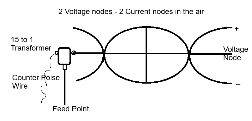
As we play with making the wire
longer we get new patterns down the wire at the same frequency as the
1/2 wave antenna and nodal points that will work the same.
With this design we will now have a full wave in the air, with
two current nodes and 3 voltage nodes. We can feed this from
either current node location.
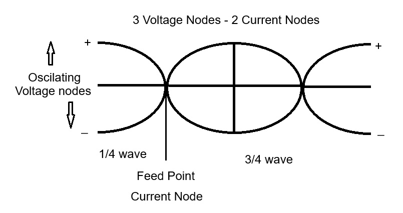 The disadvantage now is when we change the frequency the current
nodes will move so the feed point cannot feed just any frequency
no matter how we tune it.
The disadvantage now is when we change the frequency the current
nodes will move so the feed point cannot feed just any frequency
no matter how we tune it.
 By moving the feed point towards one end of the antenna wire, we
can now feed the system with other frequencies and the current nodes
are free to move.
By moving the feed point towards one end of the antenna wire, we
can now feed the system with other frequencies and the current nodes
are free to move.
 This is the basic end fed configuration. Now what
we shoot for is to get a voltage node on the far end of the wire, and
then match the impedance on the other end to the phase that lands on it.
This is the basic end fed configuration. Now what
we shoot for is to get a voltage node on the far end of the wire, and
then match the impedance on the other end to the phase that lands on it.
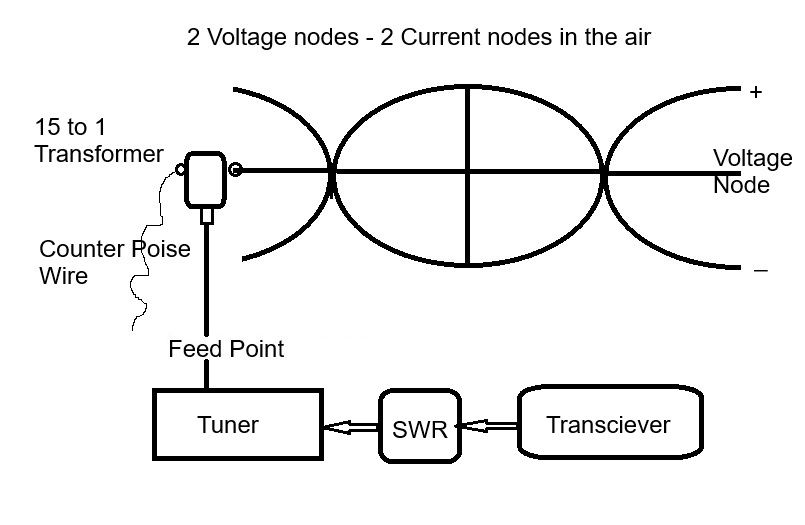
The current nodes can now move about anywhere as long as they are not
too close to the Balun Transformer at the feed point. The toroidal
transformer is inside the box and makes the voltage jump,the current
drop,and the impedance raise also on the active antenna. The Antenna
tuner
can now reach this much higher impedance, from a much lower one and we
can get all the amateur bands operating on this system configuration.We
can now make the antenna long enough for a low frequency HF band
and still fit the higher frequencies on this same antenna with more
nodes along it, and we only have to feed it on one end.
Antenna lengths and resonance using a Tuner
Impedance
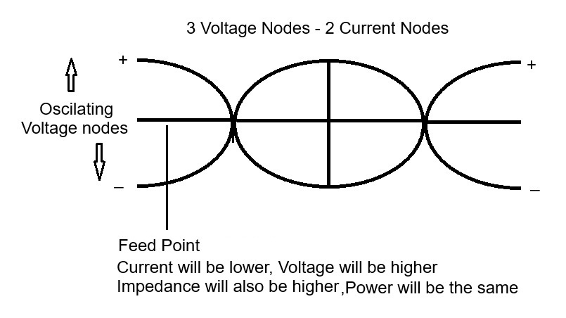
If we want to power from a voltage node point or anywhere away from the center current node we have to increase
the impedance of the feed point we are using
and this will raise the
voltage at the new feed point just as happens on a resonant dipole.
We can get good results using a 9 to 1 toroidal transformer or even greater
15 to 1 toroidal transformer, and there are many commercial ones that
work up to 1.5 kw or higher.
The impedance rises with the square of the turns ratio as I recall.
Now we feed the system from the low impedance side of this
transformer and as we change its tunning we get 4 times the change on
the output side at the turns ratio on the antenna feed point.
We can now get the range necessary to match the End Fed Antenna across all the HF bands if we choose our wire length correctly.
The center of the dipole must now land somewhere down the long wire at
a 1/4 multiple wavelength from the other end where a voltage node will
appear at the point of reflection.
That current node point can now move with the frequency along the long
wire as we change the tuner and the transmitter frequency.
These high impedance toroidal transformers can be used for end fed
or off center fed antenna systems that can tune more bands more
efficiently then a basic center fed dipole.
They hand the antenna tuner greater flexibility and keep the impedance
of the coax transmission line lower, much closer to 50 ohms but
amplify the changes as we adjust them with our tuner.

One can consult electronics training materials on-line to understand
transformers, and how the power goes through them only changing the
voltage and current,
exactly what we see down an antenna wire length.
Turns ratio converts the voltage one way and the current in the
opposite direction with a little loss in power as the energy moves
through it.
Thus we can now feed the antenna at a different point then its current node position.
We can safely move up towards or even on a voltage node and keep that out of the transmission line to the Transmitter and Tuner.
Common Mode Chokes
It is also good practice to place common mode chokes on both ends of
the 50 Ohm feed line, as the impedance on the feed line may not be very
close to 50 Ohms for some frequencies.
The chokes will reduce any radiation off the transmission line and also
reduce any noise from being picked up on the line. There is one to the
right of the main box in the photo above.
The Long Wire End Fed Antenna
If
we want our antenna to radiate RF energy it must be 1/4 wave or
longer, with a voltage node reflection at the end to get out into space
well.
The wave must pass through the 377 ohm point on the antenna in order to
couple its EM energy into the Space Fabric. This point is very near the
current node position but a little further out then the 50 ohm point.
This is how the dis-cone antenna works.
With a long end fed antenna this means we have to get at least one
current node on the wires length and one voltage node to the other end
of the wire.
If the antenna is longer we can use a tuner to get the voltage node to the end of the antenna.
In theory we can transmit any frequency that is higher with a shorter wavelength if the tuner can deal with it.
Maximum RF will be on the other end and any point between where we hit
377 ohms near any current node point, and a frequency with many
wavelengths down the wire will become directional.
In theory if we transmit into a 50 ohm dummy load the signal will
not reach very far out into space compared to a well tuned antenna hitting the 377 ohm range..
The dummy load may also get hot as it is sinking the energy into
itself. There is a time limit for this based on the watts we are
transmitting.
To add more power we must use a linear amplifier, increasing the current and voltage at the 50 ohm feed point!
Then we have to also get a tuner that can handle all this extra power.
I have the MFJ 998 and it works very well at 800 watts off my Ameritron AL-811H amp on my End fed antenna.
Thanks for reading!
Dave L
AL5X
End Document
6 - 23 - 2025