TS-940S - Repair
2017 - 1 - 30
Document by David Lowrance AL5X
I was gifted an older
Kenwood TS-940S by an Elmer. He said it was one of the best Ham Radios
he has owned. One morning he turned it on and it was just
dead.
First suspect is always the power supply, in this case.
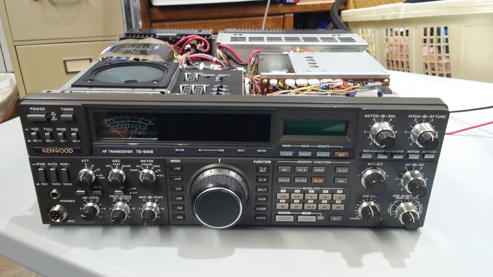
DOA - Dead on arrival - Cover Removed
Transporting myself back in time, to the era when you fixed the circuit
rather then simply changing out the broken board, you either enjoy the
challenge of comprehension, or you run away and hide in depression,
because looking under the hood reveals a system that appears so complex
that no one could really keep it all straight.
A little research, a
circuit diagram, and it became obvious that in the early models of this
radio the power supplies had several design flaws. Many Ham radios
traditionally had a separate power supply located outside the units.
This one has one squeezed into it, and appears they were not very good
at it.
Focus was quickly turned to rebuilding the AVR board and replacing opened transistors on the rear heat sync.
Lots of ideas and mods were found online for this Kenwood AVR
board. Unfortunately I did not keep track of where they all came from,
but I do wish to thank all the previous Hams who spent time designing
them over the past couple decades. I have also added some of my own here that you will not find
anywhere else, primarily moving the DC protection fuse location of F1.

AVR Power Regulator Board and Wiring Sockets

A good idea to photograph all the plugs and wire colors for
reassembly later. This Radio has high density packed components with
little extra space anywhere. 4 screws removed with a magnetic
Phillips, a whole lot of connectors that will pop right off, and
the board
lifts right out. Looks like it was designed with the ham in mind.
Initial Testing and Observations
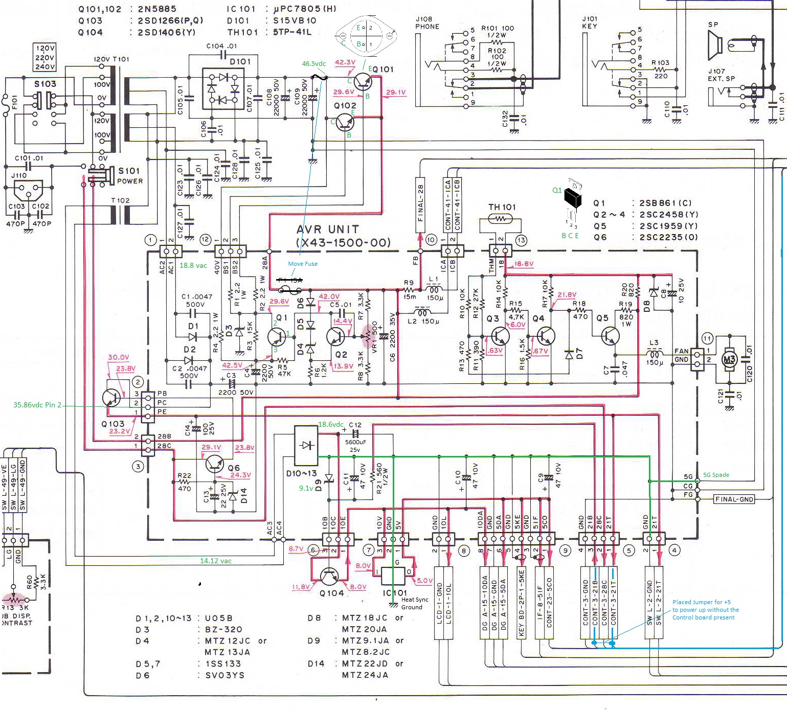
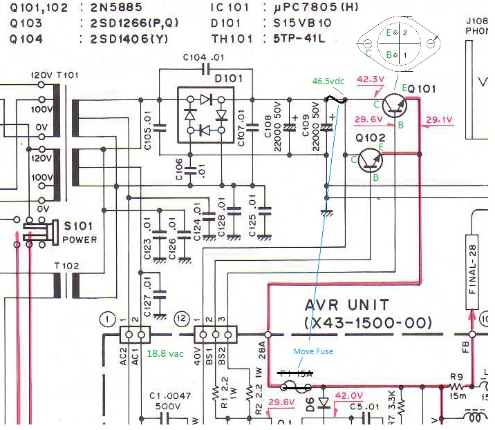
The power regulator
[AVR board] showed over voltages everywhere, 46.5 vdc on the 42.3 v
circuit location, 35.86 vdc on a 30 volt location, 18.6 vdc at an 11.8v
location, shown below in green. C12 a 16 vdc capacitor with 18.6 vdc
across it! Tiny .5 watt zener's to regulate voltages, apparently sized
too small and blown opened or shorted all through this board. It is my
opinion that Engineering a circuit to stress components over the max of
their ratings is just plain bad design. This will be quite a project
since many of these transistors are no longer available new.
A power supply that starts with 46.5 vdc then provides an output of
28.5 regulated is burning up 18 vdc as heat or wasted power at
something less then 15 amps. That is about a 39 percent waste of total
energy. This is how it was done back in the 80's. Large heat sink with
a cooling fan! Kenwood draftsmen also got the diagram wrong for a
bridge rectifier, see D101 below.
Circuit Diagram - Clipped to show the Power Supply Section
AVR Board Troubleshooting:
All testing was done with only the Supply voltage
plugs connected and all load plugs removed. Socket 5 pin 1 to pin 3 was
solder jumpered on the board to activate the 5 volt supply with plug 5
removed, shown above in blue. I left this jumper on as I have no interest in remote control of the radio and want
the supply to maintain stable voltages if this plug is
ever removed. Zener D9 had to be changed out as it was opened killing the 5v power as well. [1N4739A 1W 9.1V Zener Diode - Mouser]
I ordered a complete set of Zener diodes for all of them on this board of the 1 Watt variety. See references at the bottom.
28.5 vdc Adjustment
The 28.5 also goes through the power up circuitry [Q6] from the power on switch [connector 3] for
the lower voltage supplies, so it must be working first.
I began with only
plug 12 , 28A, FG, SG and CG connected. See the photo below. Be sure to
lift
the FB lead off to protect the finals until the 28.5 vdc is perfectly
set to 28.5 vdc per the user manual maintenance section and is stable
also on power down. When I got the 28.5 volt DC up and
adjusted, I then started adding the other AC inputs, plugs 1,2, 6,7
AC3,4 to get the lower voltages up next. Each time I added a circuit
it revealed a new set of burned out zener's and or transistors.
Obviously
the 28 volt supply had spiked upwards and stressed components all over
the board without blowing the 15A fuse. It was then also noted that if
the 15A fuse does blow it still does not remove the 46 vdc from the
regulator circuit board, and continues to then stress Q1 to the point
of
burning opened if zener diode D3 shorts out, as D3 is far too small a power
rating. D3 then shorts out rather then regulating correctly, causing Q1
to burn opened. Q1 is not heat synced either. As my line voltage is 120
vac and matches the print, the transformers are all putting out slightly higher voltages then
the print indicates for the regulator input design.
Zener Diode D3
This seems to be ground zero for the destruction of the power
supplies semiconductors! When power is shut down, Q1 and Q2 cause the
voltage to surge upwards due to the distributed capacitors in the
regulator circuit at 46.5 vdc. To cure this they apparently added a 32
volt zener D3 that then fires and limits the surge to somewhere around
31 volts.
The purpose of zener diode D3 is voltage limiting via bias current bypass. It is not a fuse or
a fusistor as some indicated was the design, that is merely what
"sometimes" happens. It is a voltage regulating device, placed there to
limit the bias on the output transistors, so they theoretically cannot go over about
31.5 vdc on the emitter or output side of the 2N2885's. The 32 volt zener should begin
to conduct when the emitter voltage of the 2N5885's is about 31
volts due to the resistor in series dropping about .5v. This should also happen if you adjust VR1 to set a voltage higher then
30.5 - 31.5vdc on the power supply. It just so happens that D3 instead often
chooses to short out, "saving the life of the finals" but destroying every other semiconductor in the power supply! In rigs where the
diode goes opened the finals may also be destroyed as the power down
surge can then go much higher. The finals are rated at 30 vdc and feed from connector wire FB.
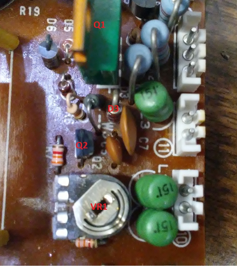
Resistor Mod Regulator Circuit
By placing a larger zener in the circuit
[1 watt], we can still get the desired effect, and it is repeatable more
times without destruction of the diode. However the two new resistors that were
added 22k and 4.7k are to change the bias response at the control point on Q1 and Q2 to operate
more closely to where they should have been and totally avoid the voltage surge
to over 30.5 vdc on power shut down, which caused the zener to get a
real workout and finally fail. This is a Kenwood mod, although they do not mention a larger zener diode which I also recommend.
Move 15A Fuse, Add Crowbar Circuit
With the addition of the "crowbar circuit" and
moving the 15A fuse location, it may also shut off the power supply
completely when you hit about 30.2 vdc threshold and you will be
changing out a
fuse instead of finals or D3, Q1,Q2,Q101,Q102 and probably the rest of
the semiconductors on the heat sync for the lower voltage supplies.
Take your time and ensure the 28.5 voltage is both stable
and will not spike on power down, before you move on to reconnect the
FB wire that powers the finals, or to work on the lower voltage
supplies. A scope on spade tip FB is the best way to observe this but
it is slow enough
to see on a VM to.
AVR Board - Before Mods

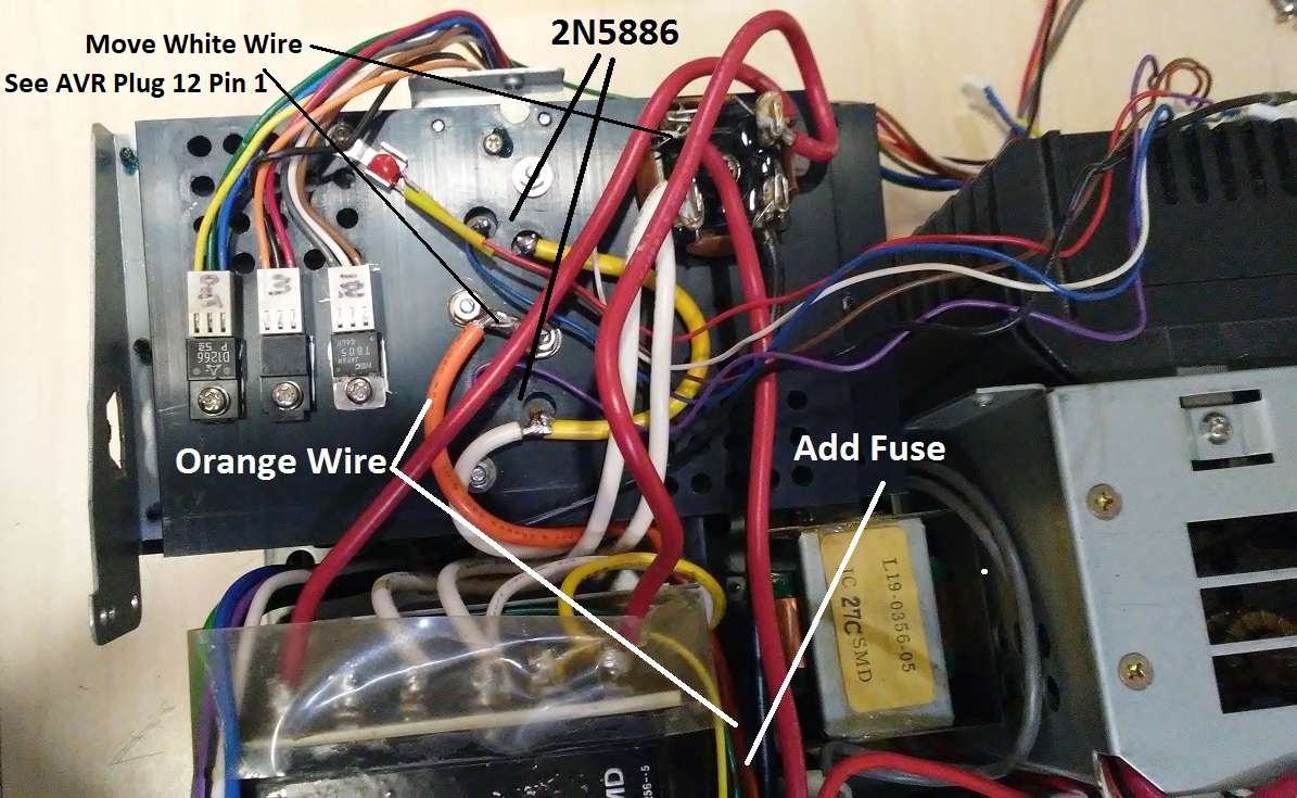
Heat Sync
The heat sync is unscrewed then lowered towards the back of the unit.
Replaced Q101- Q102 on the main heat sync panel with higher
rating transistors as they were both opened, Q101-102 2N5885 60v
replace with 2N5886 80v [ Mouser ]
While the transistors are being replaced do the fuse relocation mod found below.
I ended up changing the other three semiconductors on this heat sync as
well, shown on the left. I marked the cable plugs Outer, Middle, and
Inner [Out - M - In] so all three could be removed at once. Left to
right Q103, Q104, IC101. 2SD1266(P,Q) Ebay , 2SD1406(Y) Ebay,
uPC7805(H) Mouser.
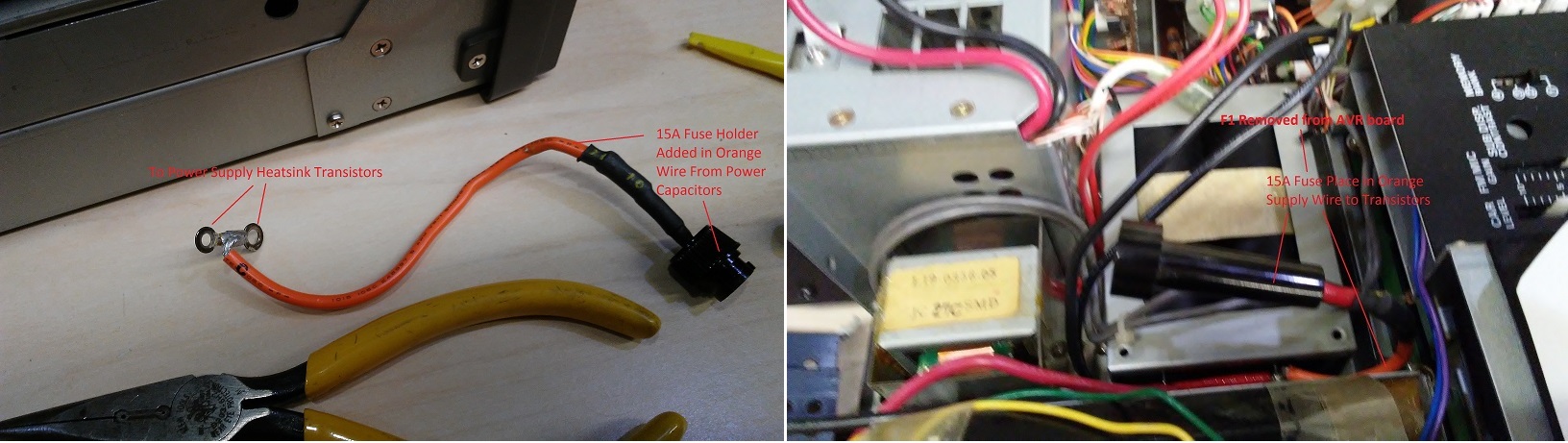
Fuse Relocation Mod
Move the 15A DC Protection Fuse off the AVR board to
the location
ahead of
the power transistors for total voltage cut off when the fuse blows.
This shown in blue above. A new in line fuse block is placed in the
orange wire
between the filter caps and the heat sync holding the two main power
regulator transistors [2N5885(6)]. Also see photos below. It is a major
design error not to protect the entire circuit with a main DC power
fuse and since we expect approximately the same current on both sides
of the output transistors this is a reasonable modification. This will
then kill the 46.5 vdc to the regulator board as well, where we have
regulating components often frying on power down. The
output transistors, in emitter follower configuration, can easily handle
15 amps, but the emitter to base voltage difference cannot handle 32
volts! If there is a short on the power we need to kill both the
collector and base to emitter voltages on the output transistors. It is
like this circuit was designed to destroy all the transistors on
failure, and it did!
Also note, the white wire on pin 1 of connector 12 [40v] from the AVR
board goes directly to the diodes and not to the transistors Q101 and
Q102 collectors, as the circuit diagram above shows. This wire must be
moved over and attached to where the orange wire to the Regulator
transistor collectors is attached on the back of the heat sync. See the
heat sync photo above. [Thank you KI7WTS for noticing this error in the
print.]
This mod can be done most easily when Q101, and Q102 are being changed
out on the rear heat sync because the Orange wire will be removed at
that time. Fuse holder must be rated at or above 15Amps.
AVR Repair and Crowbar Protection

28 vdc Regulator Circuit
Replaced Q1, [2SB861 Ebay] also added heat sync, and replace Q2, [2SC2458(Y) Ebay.]
Replace the .5 watt shorted D3 with 32v 1 watt zener diode [Mouser 771-BZX79-C30133], add resistor 22k across
it.
Place 4.7k resistor across upper half of VR1 to limit the over-voltage on adjustment setting of VR1. This is a factory mod for the early issue radios. Zener diode should conduct for over-voltage protection and not fry or
short in the process!
Added a crowbar circuit to blow the 15A fuse on 30 vdc over-voltage
condition.
BTB12
triac and a couple of 1 watt zener's that add up to 30 vdc. Shown on
the right above, and second photo below mounted on the AVR board where
the 15A Fuse used to be. This circuit was bench tested before adding it
to the AVR board to ensure it could repeatedly blow 15A fuses if the
voltage went above about 30.2 vdc. The purpose of this circuit is an
absolute
protection for the finals in the RF amplifier section rated at 30 vdc.
The new output transistors can easily handle 15 amps without
destruction so I do not expect them to fry opened again.
Note: 2019 - 1 - 20
I tested the crowbar circuit by adjusting the voltage to exceed 30vdc on the FB connector with the finals disconnected.
When the crowbar fires and shorts the voltage to zero, the 15Amp fuse does not blow. This was a bit puzzling.
Transistors Q1 and Q2 go opened so fast, current on the base of the
Regulators Q101 and Q102 drops to 3ma or less total, and the 15 Amp
fuse does not blow.
There was no damage to the circuit.
AVR Board Mods
Foil Side View

Component Side Views
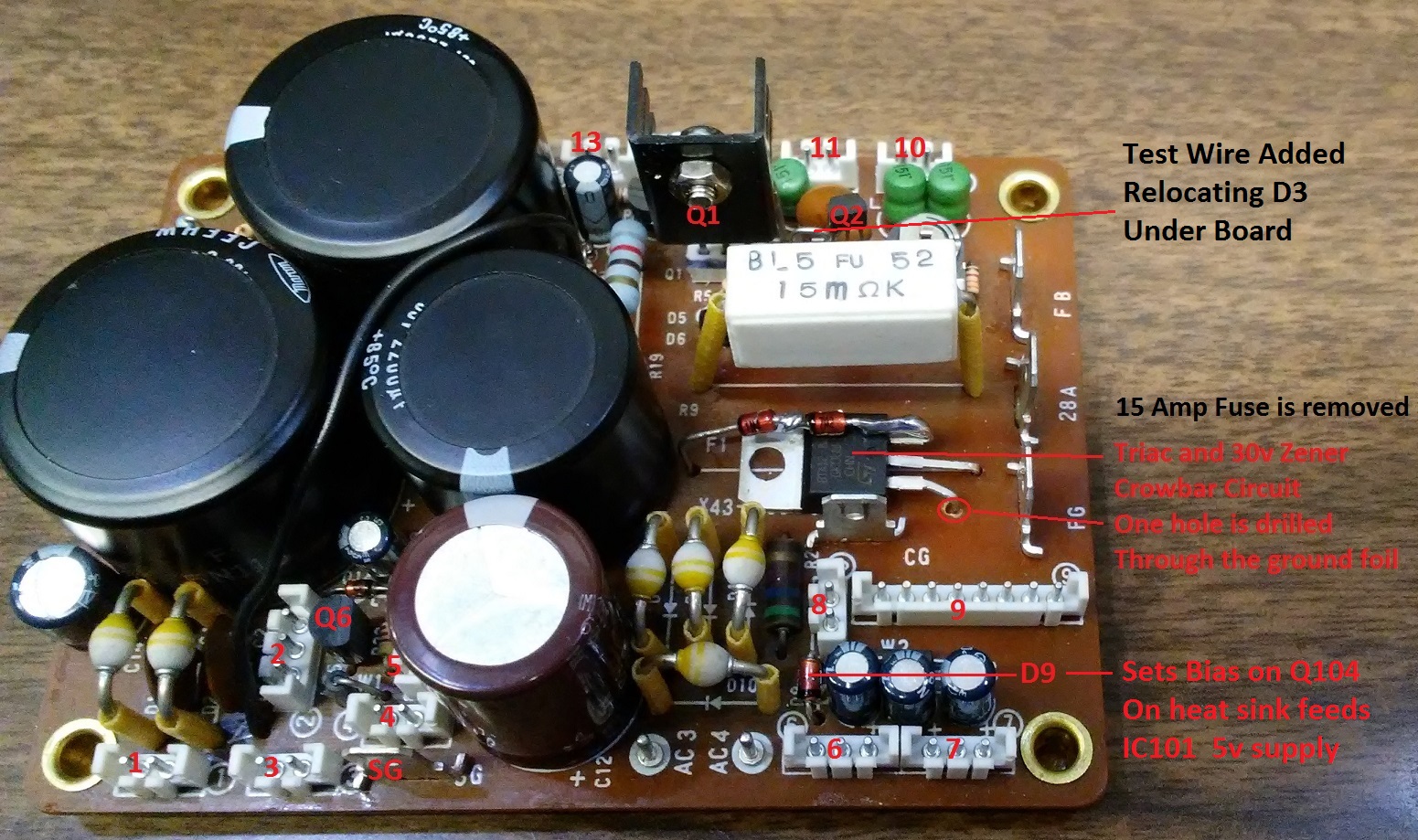
I removed D3 from the top of the board and made a wire loop for a test
point, mounting the new larger D3 zener underneath avoiding having to
drill out the holes to a larger lead size for the new 32v 1 watt zener.
The crowbar circuit is now able to use two of the holes present from
removing the 15A fuse F1 and only a new ground pin hole must be
drilled through the board.
D9's holes had to be drilled to accept the larger 1 watt zener. This required a very tiny drill bit.
Capacitor C12 6800 uF 16vdc was changed out to a 5600 uF 25v capacitor [Mouser]
This was a Kenwood recommended mod.

When troubleshooting the board, I ordered extra transistors for Q1 and
Q2 as it is the main voltage control for the 28.5 vdc. I almost
expected to blow some of them up during the process, so I decided to
mount some make shift sockets under them, by cutting up some IC sockets
which worked well. Turns out I did not need them, but decided to leave
them in. It made scoping the pins a little easier too.
Q1[2SB861] opened, Q2[2SC2458(Y)] bad, replaced. Transistors were
ordered from Ebay, as parts are out of production now. Q1 got a small heat
sync from the junk box as well.
Side By Side Comparison

Fan Mod

Fan mod, replaces two resistors so the cooling fan will come on at lower temperatures. This was a Kenwood recommended mod.
Q6 Surge Protection Mod

A 47 ohm resistor is placed in series with the input supply voltage to
transistor Q6. This mod was recommended by a ham online to shield Q6
from transients during power up and power down.
As a final note, many have found the solder joints to be less then
adequate on this particular Kenwood radio, with a high number of cold
solder joints. If you are up to it and have good solder techniques,
redo all of them when the board is out. All solder joints should shine
nicely and not have a crystalline or opaque appearance.
Power Up
All voltages now reading correct, I put the load side
connectors into the AVR board and turned on the radio. Power
up revealed the green LCD display battery was dead.
CR2032 with solder tabs on opposite sides. Clock memory cleared on
each power down, then gave strange responses on each power up. The
front panel is dropped, with the Radio setting on the edge of the
bench, to access the 2 batteries soldered just behind the green LCD
panel. The speech processor has a cable that must be disconnected to
lower the panel, seen hanging over the front.

This radio has 3 of these, two on the front panel and one
somewhere down in the guts of the inner boards that is apparently still
working.

Amazon had these 3V
Lithium Coin Batteries with solder tabs. They were used in something
called Video Game Museum. For now I had some CR2032's and stacked them
between pennies. You can solder tabs to the copper pennies then
tape them together
tightly with electrical tape and get it to work. One of those MacGyver
things you do, while thinking you will fix it later, then never do
because it works, then you forget about it.
Locate the reset switch before you close up the front panel. It is on the back right side of the board just behind and to the right of the batteries you just changed out.
Put the front up but leave the covers off.
Do a microprocessor initialize on the radio. Turn on the power with the
A=B switch pressed. If the display fails press the reset switch.

Addendum:
2018 - 12 - 29
All three batteries were replaced with CR2032 Battery holders. The batteries are all now floating behind the panel.
I needed one with total covers that shut securely and insulated the batteries completely.

These holders place two batteries in series, but if you only place one
battery into each, the second position shorts on through so you can use
them as single 3v battery containers.
As I recall I used three of these and let them hang into the wiring
harnesses behind the panel, now all three can be changed out yearly,
without disassembly of the radio at all.
Also they have an on/off switch on the side, so be sure you meter the
wires for voltage and set the switch accordingly before closing up the
radio.
Here is the Amazon item I ordered that worked.
uxcell 5pcs 2xCR2032 Battery Black Round Button Cell Coin Holder Box w Cover
Final Tests
Unit was powered up and loaded into a 50 ohm dummy load at
100 watts output. The fan came on just fine after transmitting for a
time. Function generator was also used to verify receiving on several
bands. The transceiver appears to be fully functional.
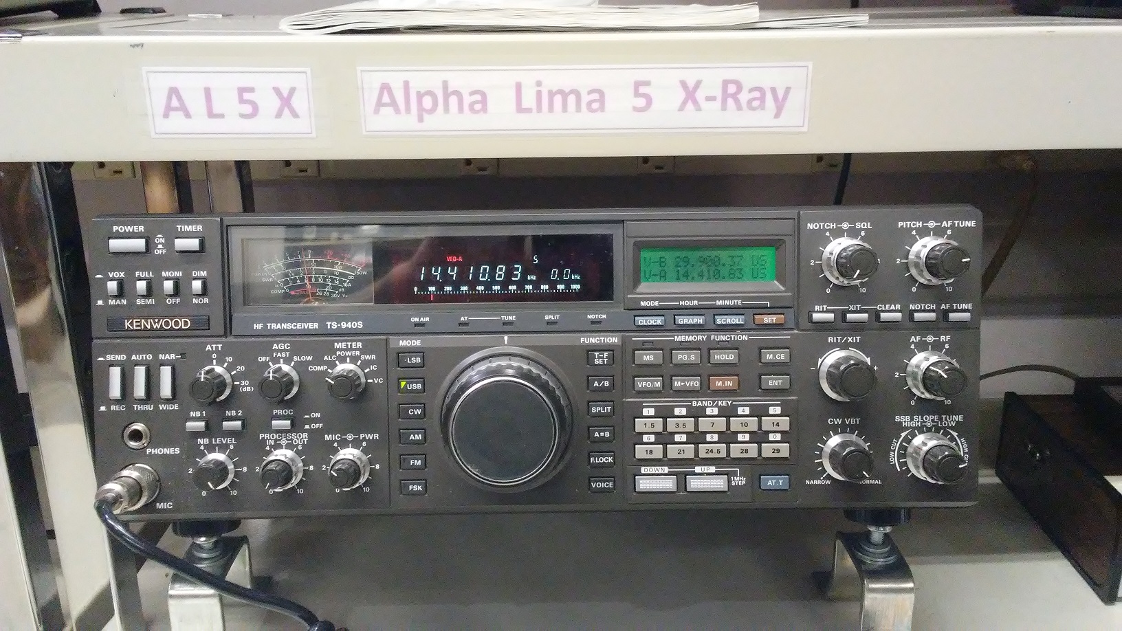
Station Setup
An original Kenwood MC-60A microphone was purchased from
DX Engineering, whom just happened to have brand new ones still in
stock!
The MFJ keyer to the right is about 25 years old and still working with the nice dual paddle.
An old stereo speaker modified with a 3.5 mm audio plug, and we have a nice sounding HF station.

References
Parts and Suppliers
[Power supply rebuild project - AVR PC board and Heat Sink power semiconductors]
Replace components [some bad]
C12 16v 6800 uF - Change out to a 5600 uF at 25v per release notes, this cap has 18 v on it. [Mouser] Done
D3 32v Zenner
BZ-320
shorted Done
D8
Zenner
MTZ18JC or
MTZ20JZ
[Mouser MTZJ18C] not done, good
D9
Zener
MTZ9.1JA [1N4739A 1W 9.1V] [Mouser 2 ea] Done
Q1 PNP Transistor
2SB861 (C)
opened [Ordered Ebay 2
ea 1/19/2017] Done
Q1 PNP Transistor
2SB861
[BD708 Better Replacement Ebay] Not Done
Q2,3,4 NPN
2SC2458Y Q2
done
[BC639 Better Replacement Ebay] not done
22K 1/8w Resistor (Added
Option)
[Mouser] Done
Q101 x NPN Power Regulator
2N5885 60v Replace with 2N5886
80v [Mouser] done
Q102 x NPN Power Regulator
2N5885 60v Replace with 2N5886
80v [Mouser] done
------------------------------------------------------------------------------
Critical AVR mods -
28.5v Over Voltage when power shut down - Crowbar Circuit - Move Fuse Location 15A
Do mods for 22k and 4.7k voltage regulator on AVR - add resistors [Done]
Fan starts on cooler temp
Do mod for fan 470 ohm and 4.7k - change out resistors 370 and 10k [Done]
Fan works.
----------------------------------------------------------------------------------------------------------
Parts ID
Transistors --------------------------------------------
Q2,Q3,Q4x
2SC2458
(Y)
[EBAY 5ea]
Q5x
2SC1959
(Y)
[EBAY 1 ea]
Q6x
2SC2235
(O)
[EBAY 20 ea]
Power Regulators on Heat Sink --------------------
Q101,Q102
2N5885
[Mouser 2N5886]
Q103x
2SD1266
(P,Q)
EBAY 4 ea
Q104x
2SD1406
(Y)
EBAY 1 ea
IC101
uPC7805
(H)
Mouser
Diodes -------------------------------------------------
[D4SC6M Dual Rectifier Diode - Replacement for D1,2,10-13 Rectifiers]
D1,2,10~13 [U05B 2.5a 100v diode NTE5801]
D5,6,7
1SS133
[Mouser 5]
Zener Diodes ---------------------------------------
D4 x 12 v
MTZ12JC [1N4742A 1W 12V][1N5349B 5W
12V] Mouser 2 ea
D8 x 18 v
MTZ18JC [1N4746A] Mouser 2
ea
D14 x 22 v MTZ22JD [1N4748A 1W 22V] Mouser 2 ea
D9 x 9.1 v MTZ9.1JA [1N4739A 1W 9.1V] Mouser 2 ea
----------------------------------------------------------------------------------------------------------
Fan Mod ( increase cooling at lower heat level, and speed up fan)
R11 470 ohm Mouser
R17 4.7 K Ohm Mouser
David Lowrance AL5X
libra_spirit@hotmail.com