Raspberry Pi 2 B - LED Matrix Driver
7 - 23 - 2015
Documenting a Raspberry Pi 2 B build, to run an LED matrix system that is 8 x 112 super bright LED's.
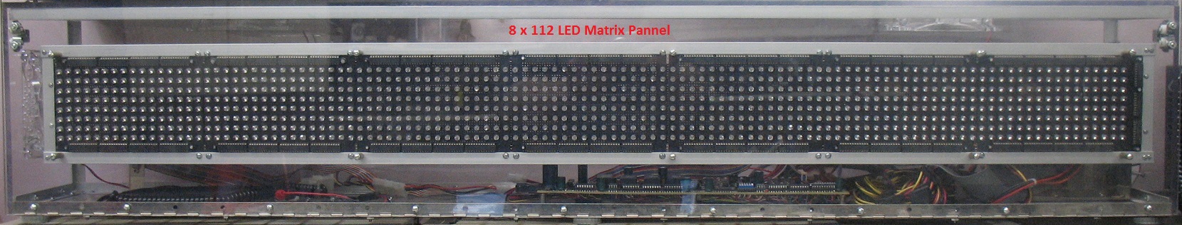
There are 8 LED driver chips on each of 7 LED boards. Toshiba
Bi-Cmos TB6270BN/BF 24 pin DIPS. Each chip drives one row with 16
LEDs and has a 16 bit internal latch with serial input chain that can
go up to 20 MHz.
On the right end are 3 driver chips [TTL 74-240] for the Latch
clocking and Output enable leads. The Logic is all 5 volt, and the LEDs
use 3.3 volts from the PC power supply.
Brightness control can be achieved with an external resister [presently
1k] on each chip to set the LED constant current supply, and also by
using a strobe sequencer on the 8 Output Enable leads.
The buss interface uses 8 data in pins, 8 output enable pins for
strobing brightness, 1 clock pin, 1 Latch enable pin, and
two blank display pins.
If we want to use the same control chips, we will need a total of 20 pins used in our feeder cable [40 pin cable].
We must remember to blank the display on power up, so a delay
circuit may be required for that on our interface board.
A ground is carried on every other pin on the 40 pin connector to the LED panel.
There is also a power cable with plug to the PC power board.
This was a high school senior project in 2005, and since then the
controller board has lost it's brains. It was designed and built with
good documentation, but cannot be accessed anymore with our newer
computer ports for troubleshooting or control.
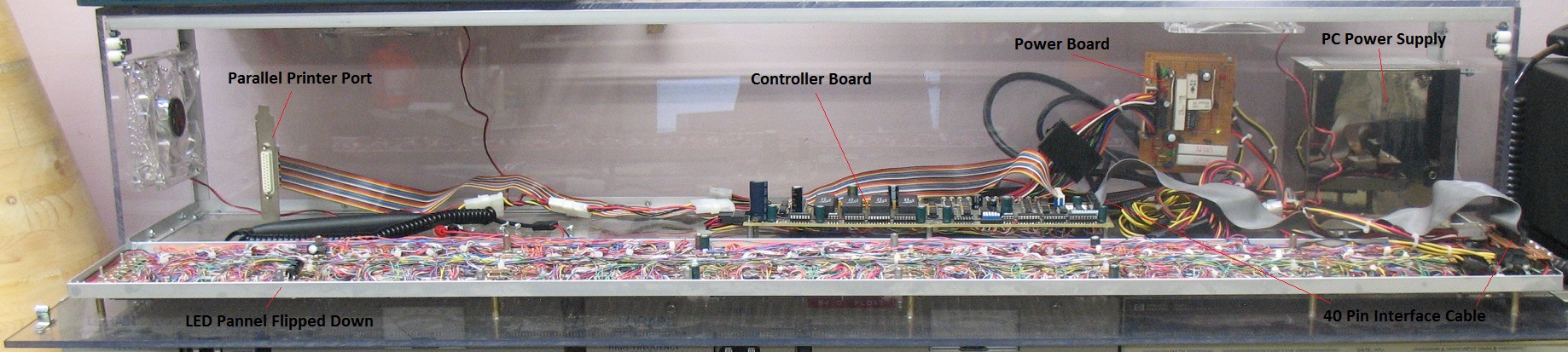
You can see the display boards are hard wired, as is the controller board, and all chips were socketed for fast replacement.
The older controller board was accessed via a parallel printer interface, and none exist on new computers.
I will toss out the old controller board and replace it with the Pi,
adding wireless network connection, wireless keyboard and mouse.
The only cable leaving the LED panel will be a monitor cable for temporary programming and the PC power supply cord.
I am hoping the Pi 2 can be powered from the 3.3v and / or the 5v supply.
The Raspberry Pi 2 is a computer that uses Linux software. It has a 40
pin IO port for experimenters. The hard drive is a compact micro SD
chip with 8 GB of storage.
I am hoping I can write a driver to run the panel, and possibly build
an interface board between the LED drivers and the Pi using only a few
chips.
I will have to use logic level shifting to move from the 3.3v outputs
of the Pi to 5v TTL logic of the LED driver board. The two ports on the
Pi that are attractive are the I2C and the SPI, both serial ports.
I will try to list most of the parts I will be using with URL's from Amazon.com or other vendors below.
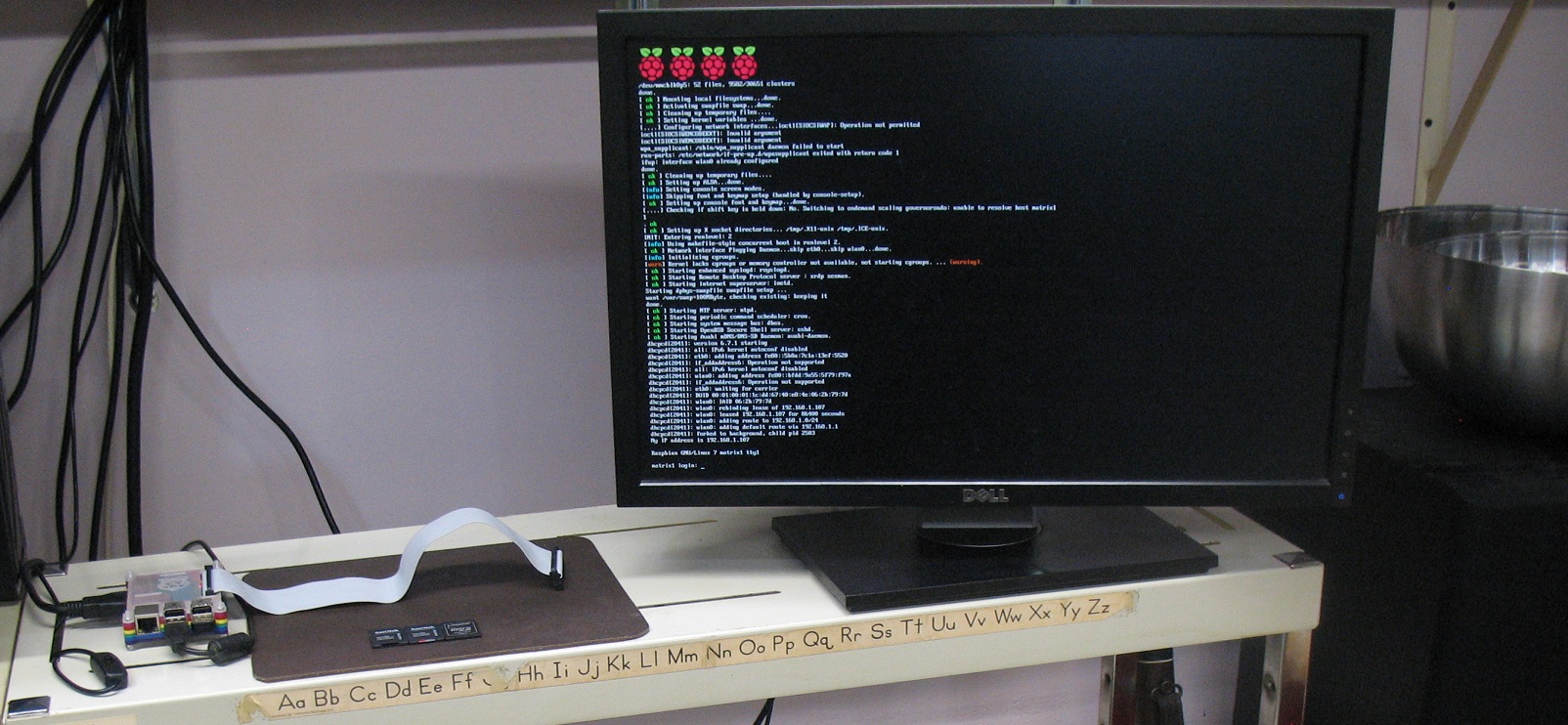
Showing the boot screen to command line editing mode, for Linux access.
Showing the Pi 2 B assembled from the kit.

Amazon.com
Eleduino Raspberry Pi 2 (1GB) Super Starter Kit
This will be used to design the basic interface boards. Another bare Pi
2 B was ordered to go inside the LED sign box. It will not need a cover.
Showing the Pi Windows screen mode and all the beginning components of the project.

Amazon.com Wireless Keyboard Mouse
Logitech Wireless Combo MK520
Dell Monitor 1920 x 1080 with USB hub and DVI or VGA input.
Keyboard dongle is plugged into a USB on the monitor.
Monitor Cable
Gefen DVI to HDMI Cable 6 feet Male-Male
This conversion cable works with the Pi 2 B to drive the Dell monitor with a DVI port from it's HDMI port.
As I understand, just any cable may not work.
Raspberry Pi 2 C
I was quite amazed, that for it's small size, all the features the
Pi 2 B offers. Standard PC components all interface very easily,
including the wifi, wireless keyboard, and mouse.
There are many online tutorials for the Pi that can get you up and
working. Here is the starting point, from the people who designed this
system board.
https://www.raspberrypi.org/products/raspberry-pi-2-model-b/
On the down side, I will have a large learning curve in mastering the
Raspbain Linux command line interface, and creating the software driver
for this project.
I am fluent in C ++, but from a Windows Operating System environment.
Interface Board
Old Controller board was removed.
The new Pi with copper heat sink, is mounted on the back Plexiglass
wall, and the new interface board on the floor below, with lots of
room for circuit development.
First order of business to get the power feed to the Pi and bring it up.
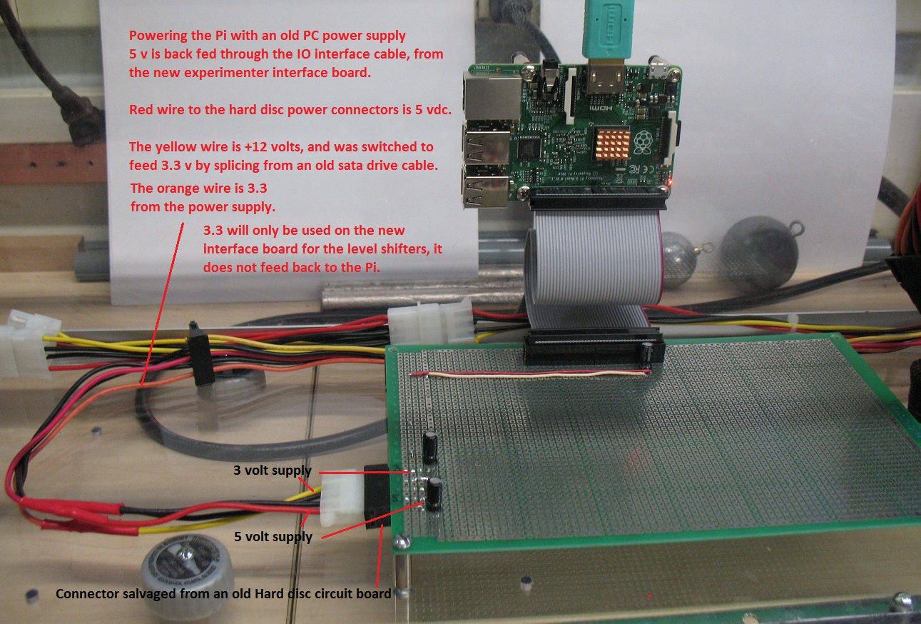
Note that the old hard disk connector provides 4 wires, yellow +12, 2 each Black grounds, red + 5.
The old sata drive power connectors however have an orange lead that provides +3.3 vdc.
I opted to do a splice, orange to yellow, dropping the +12 and delivering the +3.3 to the board on the yellow connector wire.
The Raspberry uses 5 volts and then generates it's own 3 volt supply to run the logic on the board.
The logic will have to be converted to 5 volt for the interface that drives the LED display logic.
I will have to use level shifters to accomplish this, and they will be
fed from the 3.3 on the interface board, rather then from the small
regulator on the Pi.
Also note the de-spiking capacitors on both power lines to the ground
buss and one near the Pi interface cable. This is to eliminate noise
from the power crossing between chips, and is a good digital chip
practice.
I now have power on the Pi from the older type PC power supply and it comes up, as you can see from the lit LED on the Pi!
Interface board Progress

I have set up two interface chips to expand the I/O ports of the
Pi, using level shifters to drive the 5 volt logic of the chips from
the 3v SPI buss on the Pi.
I have placed two 40 pin connectors on the experimental board, so there
is room to build two different circuits. One will use the high speed
SPI buss, on the left side, the other will access an I2C module from
the Pi expansion stack to be added later when the 20 pin connector
cables arrive.
I want to compare the speed of the two different buss's and have option
to drive the LED board with either one by moving the cable between
these two connectors.
A driver chip will be added at the bottom in the black 14 pin socket,
as the CLK clock, and LE Latch Enable leads have to drive 8 inputs each
on the LED display board.
The data and chip enable leads will only have to drive one input
to the display board, so the I/O expanders should be able to handle
that without any aid.
MCP23S17-E/SS SPI interface chips and SSOIC adapter boards - Amazon.com
Much difficulty was encountered in soldering the small 28 pin chips to
the SS0IC boards. I ruined the first 3 chips and hope the last two are
good, after learning how to solder these tiny surface mount chips from
videos on youtube.
We shall see if they work. If possible I would order larger chips next
time, but these were not available anywhere I could locate.
SparkFun parts
BOB-12009 Level shifter boards - 2 each - 8 shifters
PRT-13054 Raspberry PI GPIO Shrouded Connectors - 2 each
CAB-13028 Raspberry Pi GPIO Ribbon Cable 40 pin 6"
Proto board was from my "save it storage box" when we first built the unit 10 years ago.

Bottom of the proto board showing all battery and grounds now run in.
Orange wire is the 3 volt supply for the level shifters. Bare wires are
gounds to the outer foil, that is grounded all the way around the board.
Red leads are the +5. I used 24 gauge for all the power and ground runs.
Note on the cable connectors for the LED display board one side of all
the pins are a ground to eliminate noise on the cable. This leaves 20
active pins.
The two I/O expander chips will give us 32 outputs to choose from.
LED Board Pinout Detail
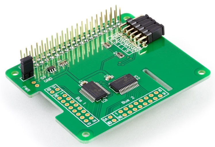
This board was purchased for the i2c interface and plugs onto the pi itslef.
2 each 20 pin ribbon cables are then used to extend the ports down onto the IO interface board.
Pinnouts are layed out below in the next diagram, showing cross connects.
Raspberry Pi 2 model B IO Pi Plus


Programming Reference
Port 0x20 Bits GPA 0-7
Screen Data, vertical line 8 bits on = Hi
Port 0x20 Bits GPB 0-7
Unused
Port 0x21 Bits GPA 0-7
Strobe Leads, Horizontal Line 8 bits on =
Low
Port 0x21 Bits GPB 0-7
Bit 7 Blank Display - Hi = Display on
10000000
Bit 6
Clock Lo
= Edge Trigger 01000000
Bit 5
Latch Enable - Lo = Active
00100000
Bits 0-4 unused
00011111
Testing Hardware
i2cset -y 1 [Port 20 21] [0,12=A 1,13 = B] [Data 00 FF]
Set ports 20 21 A B to Output Mode
i2cset -y 1 0x20 0x00 0x00
i2cset -y 1 0x20 0x10 0x00
i2cset -y 1 0x21 0x00 0x00
i2cset -y 1 0x21 0x10 0x00
Place Data
i2cset -y 1 0x20 0x09 0xFF // set all bits GPA = hi
Strobe All Banks On
i2cset -y 1 0x21 0x09 0x00 // set all 8 bits GPA = lo
Display On
i2cset -y 1 0x21 0x19 0x 0C // Blank On - Clock hi - LE low
Clock Data Into Latches
i2cset -y 1 0x21 0x19 0x0A // Clock to low
Getting the software drivers for C language control of the i2c I/O ports
sudo raspi-config [or set up system config from NOOBS startup menu]
set I2C bus active
set enable ssd for remote connection
set keyboard and language to en-us, delete uk
set local time zone and time
User: pi
Password: raspberry "change this one"
Host Name LED-Sign
Local Router Setup
LED-Sign Raspberry
7c:dd:90:8c:ba:0f
192.168.1.120 [locked in local internet router as DHCP for
this hardware address]
startx: Set up ip access to my wireless router in the startx overlay on
upper right of screen. Programs the wireless lan usb for you and
connects you to the internet.
i2c Tools and Missing Config File Text
sudo apt-get update
sudo apt-get install i2c-tools
The NOOBS leaves out some necessary i2c changes to other files, that were hard to find, to get it working.
They are in bold below and had to be added to these files manually for the GPIO port and i2c testing to complete.
https://learn.adafruit.com/adafruits-raspberry-pi-lesson-4-gpio-setup/configuring-i2c
Installing Kernel Support (Manually) nano is a text editor.
Any lines missing must be added.
sudo nano /etc/modules
i2c-bcm2708
i2c-dev
Control-X Y <return> to save changes
sudo nano /boot/config.txt
dtparam=i2c1=on
dtparam=i2c_arm=on
sudo reboot
Testing the port access :
sudo i2cdetect -y 1
Port 20 21 are 0x hexidecimal values, and show up in the detection chart.
Previous to these additions all I got was "dev file does not exist."
I wish to work on the system remotely now.
Remote connection - Windows PC on same network
sudo raspi-config [enable ssd remote connection]
sudo apt-get install xrdp
sudo service xrdp stop
sudo service xrdp start
sudo service xrdp restart
sudo reboot
Once the service is active on the raspberry, now set up a Remote Desktop Connection on your PC to 192.168.1.120 and then log in.