An HF Go-Box for Field Day Featuring Icom's IC-7300 HF Radio and MFJ's MFJ-929 Tuner
Amateur Radio Emergency Services
For Operation Reference:
A builders blog
AL5X Dave Lowrance Sitka Alaska
Document Updated 12 - 9 - 2020
Sitka Alaska
Sitka Alaska is on Baranof Island, 90 miles long and 30 miles
wide, a
triangular shape. We have 14 miles of highway and a few more miles of
mountain road. If you go out anywhere from town you will most likely be
on a boat or a plane.
Two other communities share the Island, Port Alexander, and Baranof Hot
Springs, along with some smaller aquaculture sites like Port Armstrong.
With the exception of a few local trails that terminate in canyons or mountain tops,
the terrain over most of the island is very remote and mountainous. While we have
4 repeaters for VHF UHF if you are near Sitka and have reasonable line
of sight, that mode is not really reliable for anywhere else on or
around the Island or two adjacent islands. 80 meters has been our best method in the past few
years for evening Nets, and some mornings we find 20 meters useful.
Equipment
[Gator 6U (GR-6S) shallow version 14.25" deep]
I wanted an HF unit, well equipped, transported most
likely by
car or boat, at about 50 pounds or less.
Main importance, functionality and reliability, being able to
set up quickly anywhere if necessary for an extended period of time.
I settled on a gator 6U (GR-6S) shallow version
14.25" deep. It will fit on a table with room in front for paper work
or donuts and coffee.
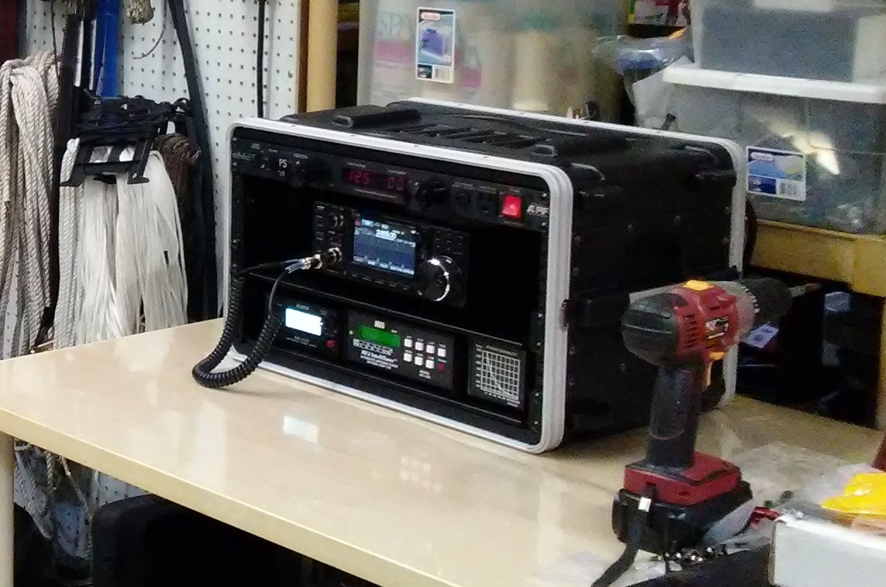
It all just fits into the Gator 6U shallow box, with the connectors out the
back landing inside the rack area. I used a 90 degree elbow on the
IC-7300 HF Antenna port which may not be necessary.
[IC-7300]
IC-7300 radio with two 8 ohm MFJ cleartone speakers
set back into the case for a more large speaker sound.
[Memory channels]
The Icom IC-7300 has memory channels you can set up for all the
Nets, and step through them with easy up down arrows just above the
tuning knob, and on top of the mic.
These channels can be programmed with a USB cord to a laptop or PC, or from the front panel buttons.
[Band Scope]
The band scope will show activity across the entire bands
to spot anyone out there who would be active.
[Dual Speakers]
The IC-7300 will drive audio into 4 ohms or 8 ohms, so the
speakers can be bridged using a Y splitter [Monoprice 107203 3.5 Mono
Plug to 2 x 3.5 mm Mono Jack Splitter Adapter, Gold Plated] plugged
directly into the rear speaker jack.
2 each MFJ Cleartone speakers. Speakers were mounted on 1/4" spacers to bring them up to the radios
height.
[Icom MB-118 optional mounting bracket]
Icom MB-118 optional mounting bracket for the
radio to be bolted down to the shelf firmly.
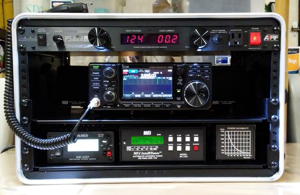
[APF PS4X4pro]
The AC power monitor at the top takes up 1U and is an APF
PS4X4pro, it shows the state of the generator power before
switching on the Alinco
power supply by using the meter preview key on the left side.
[DC powered LED strips]
The pull out light bars work off the 120 vac supply. 2 each 12 vdc "stick on" LED strips are added for lighting with a toggle on the back panel so we have emergency lighting from either AC or DC power.
Battery posts for external 12v battery with cut off breaker on the rear panels.
Checking the software revisions I discovered the radio was up to date.
I transfered the programing from my home base IC-7300 right into the Go-Box IC-7300 using a 32 GB SD card!
The front mounting hole strips and the upper and lower trim was
painted with a flat black spray paint, after carefully taping them off,
to match the panels.
Bottom Shelf
[AC Infinity Vented Cantilever 1U Universal Rack Shelf 19" x 10.5"]
[Alinco DM-430T 30 Amp power supply]
[MFJ-929 autotuner] (two antenna ports)
[MFJ-264 1.5 kw dummy
load]
The 1U 19 inch shelves are 10.5 inches deep and just fit the case with
1.75 inches spare to the rear to drop a wiring harness past before we run
into the rear panels.
The cable ties seem to be holding pretty well on this shelf , also was suggested using industrial Velcro to attach them.

Getting the IC-7300 to communicate with the MFJ-929
Recommend you test out the radio with the tuner before placing
them into the go-box. This MFJ tuner is very flexible compared with
older models, and has both hardware jumpers inside and software
settings from the front panel that must all be set correctly for the
radio model.
1 - If you want the IC-7300 radio to power up the MFJ-929 tuner
through the interface cable MFJ-5114I pull the cover off the box
and ensure [JP1 jumper] is installed. With that jumper installed you will
not have to run battery to the tuner independently. I had to solder a
piece of wire between the two foils on the board. The
location of these foils requires a thin solder tip and a steady hand,
as they are down near some components near the rear panel. [Page 9 in the manual JP1]
2 - Go into the [MFJ-929's software and configure it for an ICOM
radio interface]. Press the MODE button for 2 seconds to get into
this menu system then step down to the radio interface selection. [Use mode button and C-DN and C-UP] See
pages 16-17 in the manual, which can be downloaded from the URL's at the bottom of this page.
Test the radio and tuner into the dummy load on antenna 1 for functionality before placing them into the
box, as you may have to remove the tuner cover for jumper settings.
Ensure you have the correct interface cable also for the ICOM interface.
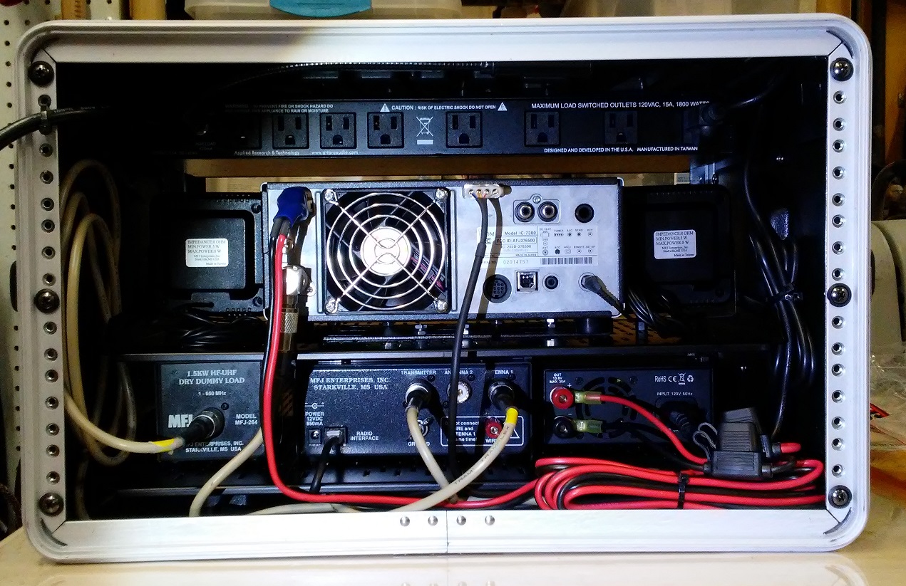
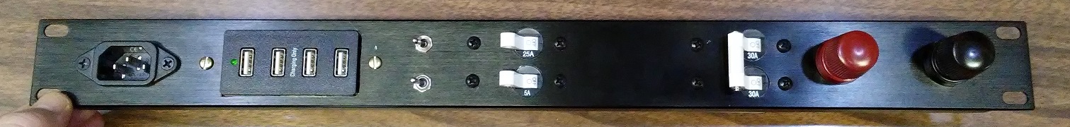
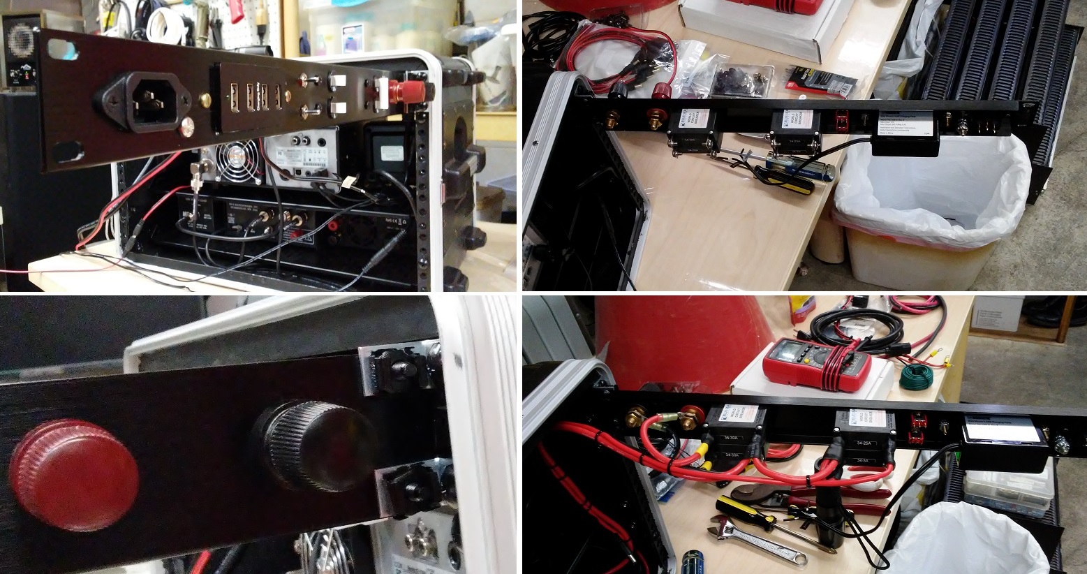
Rear Views
Showing all the connectors.
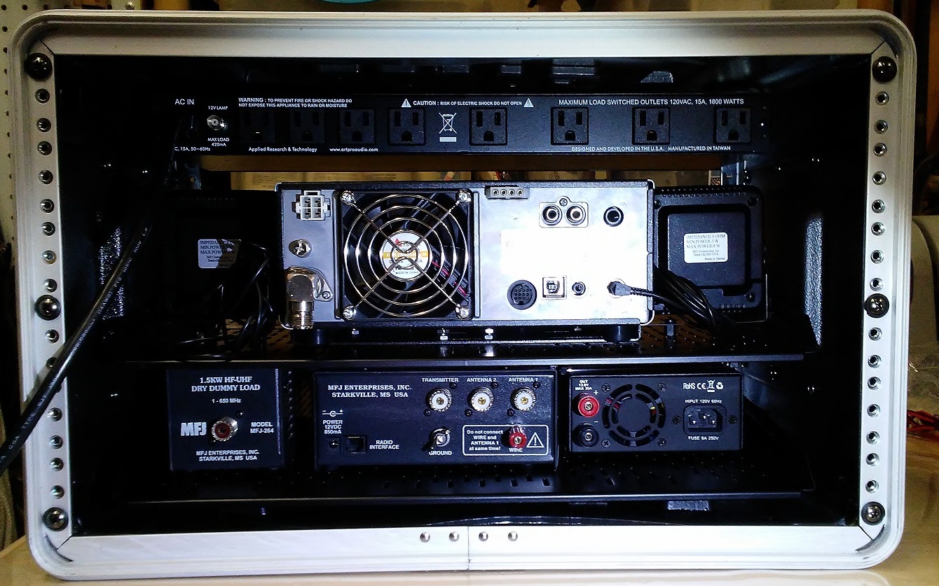
This is what the trim and mounting holes looked like before painting them black.
Showing the initial "testing phase" wiring.
So far I can still carry the box with one hand! 47 pounds.
Rear Panels
[Resettable marine breakers from Blue Sea Systems].
A row of marine breakers along the top rear of the box. For reliability, leave no one time fuses in the system!
The IC-7300 has 25 amp
automotive fuses in it's power cord, replaced
with a [25 Amp marine breaker].
[External Battery Posts]
Battery posts on the back panel for attaching an external 12vdc car battery, with a shut off isolation breaker [Blue Sea A-Series Toggle Double Pole Circuit Breaker 30Amp].
[4 Aluminum panels].
AC Infinity Rack Panel Accessory Blank 1U and 2U 19".
Center two
panels are 2U blank or vented for easy removal and access, while the DC
power is controlled along the top 1U area , out of the way for access
of the rear components.
The lower 1U holding the lightening arrestor
for the antenna, a small ground bar, a USB port extender for
programming the radio or laptop control of operations, and some Key jacks for all possible key types.
USB Charger
Addition of a [MAGNADYNE Wall Mount 4 USB Charging Ports] unit for cell phone charging, with a [Blue Sea Systems Toggle Single Pole 5 amp circuit breaker] and internal led lights on the same breaker to reduce breaker count.
[Key Jacks]
The
IC-7300 has a 1/4 inch stereo socket. My Bencher paddle key was modified
to a newer 3.5 mm jack for the Yaesu FT-891.
I would like the ability to plug in almost any key without messing with
wiring changes, so will mount 2 or 3 various jacks in a row on the rear bottom 1U panel.
[USB Programing Port]
[1 foot StarTech Panel Mount USB Cable B to B - F/M USB extension cables] for rear mounting the USB port in the rear bottom plate.
This cable caused RF trouble on the 40meter band. I wrapped a layer of
Aluminum foil over it and then black tape, and it fully cured that
problem.
If you can find a USB extender cable that is panel mount, with shielded cable that would be a good thing.


Components arrived - Looks like they will
all fit in the 1U panel. LED strip in front and power socket above
so shelves can be removed without disturbing the "stick on" LED
strips.
Components mounted into DC Panel.
DC Wiring Harness Diagram
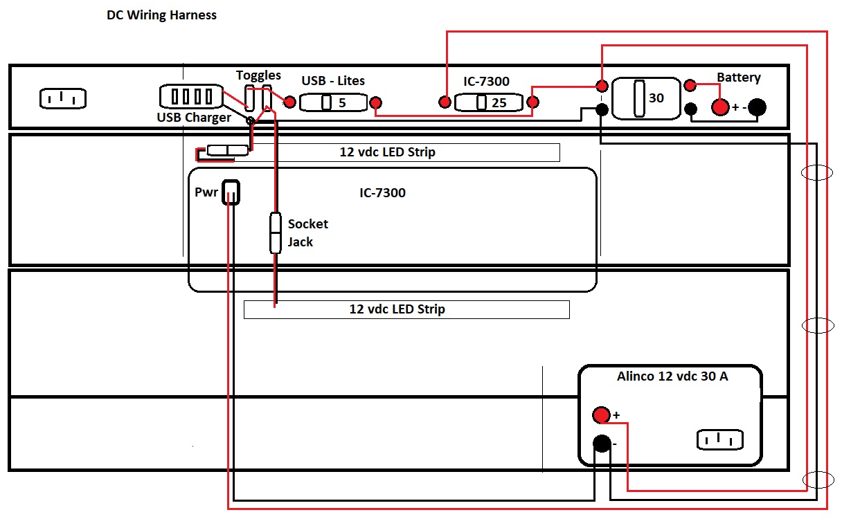
The wiring harness will route all the wires bundled up the
right side bottom to top. The upper panel can be swung out to the
right and attached with right angle clips for access and wiring.
If you are working on a 12 v external battery through the battery
posts, and there is no AC power, the [ Alinco 12 vdc supply will act as a
voltmeter. From the voltage you
can assess the battery state.] [This is no longer true with the newer Alinco 430T.]
10 volts or below will do permanent damage to an automotive lead acid
battery. To fully charge it up 14.5 vdc is applied for a time of
equalizing then it is reduced to 13.8 to float. The unit can be used
as a battery charger, with voltage adjustment on it's front panel. This
is the reason to have one of the adjustable voltage supplies. A
low voltage alarm can be added across the power supply if desired for
an audible sound at a preset voltage, however the
digital voltmeter is on the front side.
With AC power applied, if the battery is very low, you can shut
down the radio equipment and reduce the voltage on the Alinco
charger bringing the battery up slowly. You can monitor the
current and keep the battery cool as it charges. A car battery can
be charged at 30 amps, automotive alternators are usually rated at
60 amps. The battery isolator breaker is sized to protect the
power supply during battery charging, as well to protect from fire from
battery discharge if there is a short in the power supply.
Note: The in line automotive fuses were removed from the power leads to
the
radio, only the positive side goes through the 25 Amp panel
breaker. The external battery posts however both go through the
30 Amp panel breaker. If the polarity of
the battery is reversed, this will limit surge current to 30 amps then
blow the breaker between battery hot and cabinet ground. It is expected
this surge will pass through the Power supply diodes and that they
can handle the 30 amps.
Note: The Radio power wire harness and plug for the IC-7300 can be
replaced with the Yaesu FT-991 power cord and plug at a fraction
of the cost. I like to keep the original in case I later place the
radio in the shack.

1ea - Coaxial Lightening Arrestor PL-259 Sockets [Through panel mounting]
1ea - Blue Sea Systems Common BusBar 6 screw grounding [Mounted inside panel]
1ea - Grounding Post [sticks through the panel on both sides]
1ea - Through panel AC cord socket 15A 250V [Top Panel AC power cord is cut and soldered here, a new 10 foot 15A power cord with correct plug replaces it and can be removed]
2ea - AC Infinity Rack Panel Accessory Blank 1U Space 19" [Bottom and top panels]
Misc - Green Ground Wire
Note: The green ground wire shown going to the AC plug on the upper panel was not placed there.
The Alinco power supply connects this wire to the Negative DC post through the AC power panel.
The green wire was run to the negative DC post on the rear of the
Alinco power supply, connecting front side rack to rear side rack
ground.
All the panels now measured continuity to the Ground post, as the Gator case is an insulator, this was a factor in grounding.
As Built
Radio Shelf - AC Power Shelf

Automotive Led strips placed on bottom front edge of Radio Shelf
and AC Power Panel. Black T-Rex duct tape strips and small black cable
ties were used to secure the wires, and to make a blind for the AC
panel which does not have a lip extending down. The tape overlaps the
LED strip about 1/8 inch on the front side, and blocks the light from
shining forwards in your face. After research I found that T-Rex has the
highest holding power of all the duct tapes, and it should hold up well.
The radio shelf has a nice lip downwards to the front as a blind,
led strip fit well behind it. Plug ended power wires were used so
the shelves can be removed without disturbing the LED strip wiring.
Key
As
every HF ham operator knows, CW is the last line of communication in
emergency situations if propagation will not support SSB.
I spent some
time cleaning up an old CW Key I had around since the 80's, and then
threaded two holes in the shelf to screw it down securely.
A little Brasso, a lot of time, and it looks almost new. Never knew there were so many parts in a key!
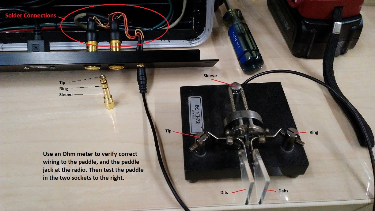
It is
wired to the jacks on the rear lower panel in parallel with tip and
sleeve, with a video power disconnect jack at the rear of the shelf.

Rear Panels
Wiring Method Upper 1U panel
Small 90 degree standoffs were used to hold the panel in place and
all wiring was routed to one side of the case so it can be swung out to
work on, as the wiring harness was constructed.
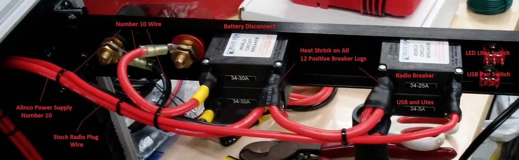
Number 10 wire is specified for 30 Amps DC to go any reasonable
distance. Yellow Sta-Cons were crimped then soldered on the ends. All
12 Volt DC positive joints were covered with Heat Shrink. The 5 Amp
circuits used smaller wire.
Wiring Method Lower 1U Panel

Ground Detail

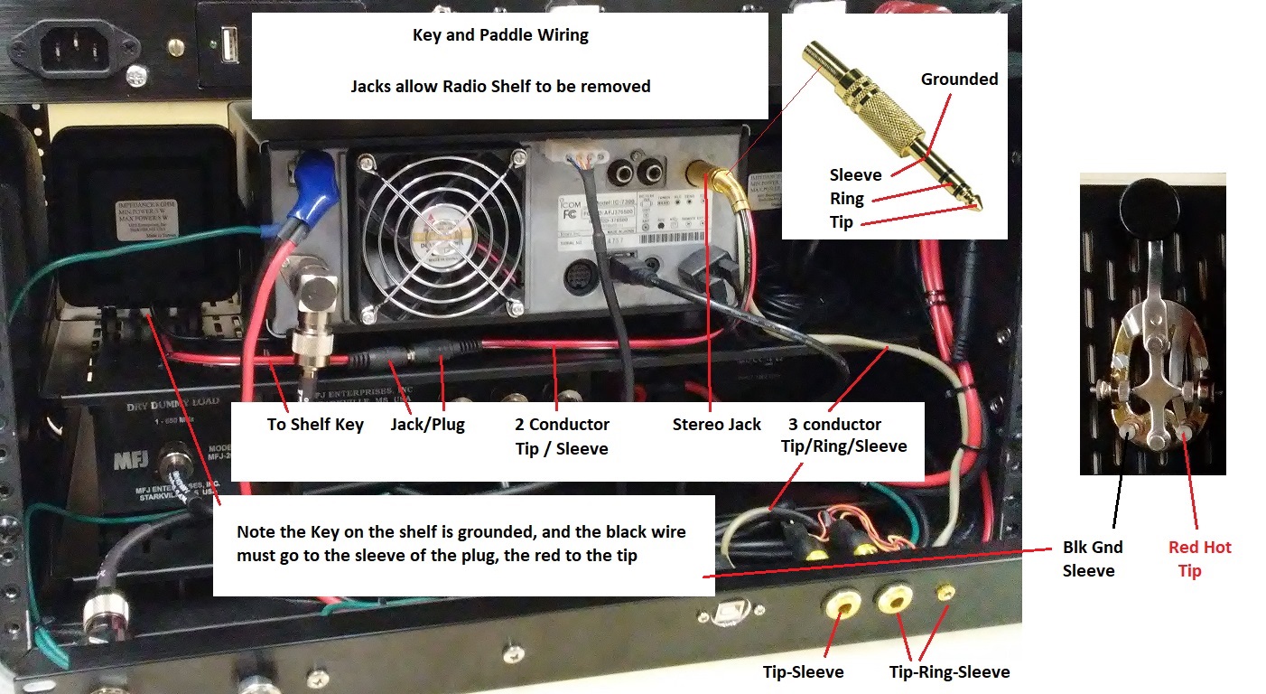
Key and Paddle Wiring Layout
Rear Jacks
Final Assembly photos
Rear View

The middle three panels can be removed to access all the wiring. Lower
panel will tip down on the desk, upper panel can be turned to the
right and secured with the 90 degree brackets.
The Antenna 2 connector is one end of the lightening arrestor. The key
and paddle jacks are wired in parallel to a 1/4 inch gold plated stereo
plug that inserts into the back of the radio.
Key jack only gets two of the wires Tip and Sleeve, the paddle jacks get all three Tip Ring and Sleeve.
Front View

The LED lights worked out
well, the angle just illuminates the Radio buttons, lower shelf also
excellent visibility for dark operation times.
ICOM Microphone Storage Solution

I tested the magnet storage idea setting the Gator case on both sides
to see if the mic would fall off the magnets, and it held with the two
magnet stacks, but was a little loose with only one set.
The Gator front cover can go over the case with the mic still attached
to the radio. Will see if the mic survives this magnetic effect! LOL!
[I worked on this solution for a long time, and even attempted to
attach a standard mic button, but could not even get the screws on the
ICOM mic loose to open it.]
Final Weight 51.5 pounds.

References
Parts List Go Box Parts Listing w/Prices
DX Engineering [ships to Alaska USPS] https://www.dxengineering.com/
73'
Dave Lowrance
AL5X