Sweet Related Drawings
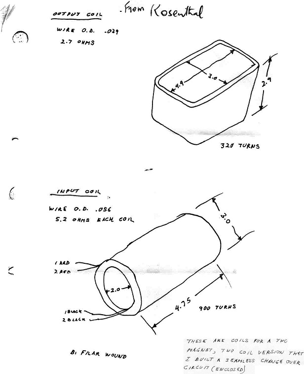
Showing first an output coil which is square, and an input coil setting inside it which is cylindrical.
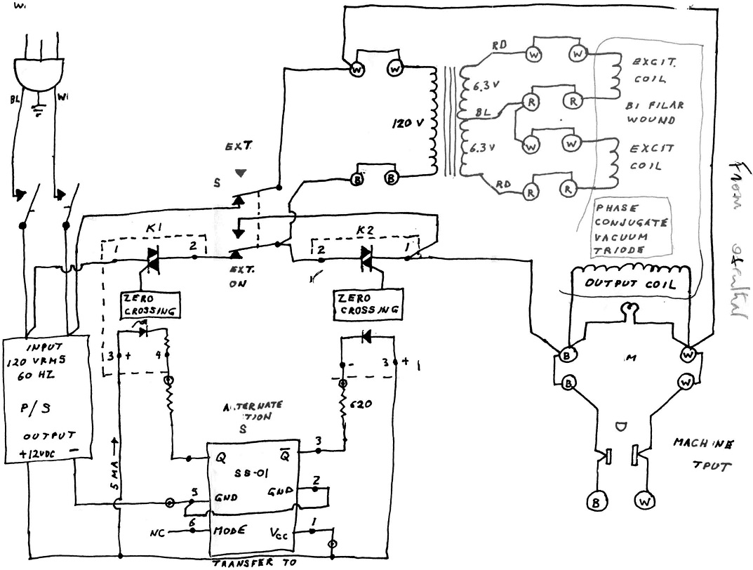
Ext switch, showing that after the coil arrangement is running, the pulsing and AC power from the wall is removed from the circuit.
The only elements running the system now, the coils, the magnets, and the light bulb.
Output coil is wired directly back onto the input of the transformer.
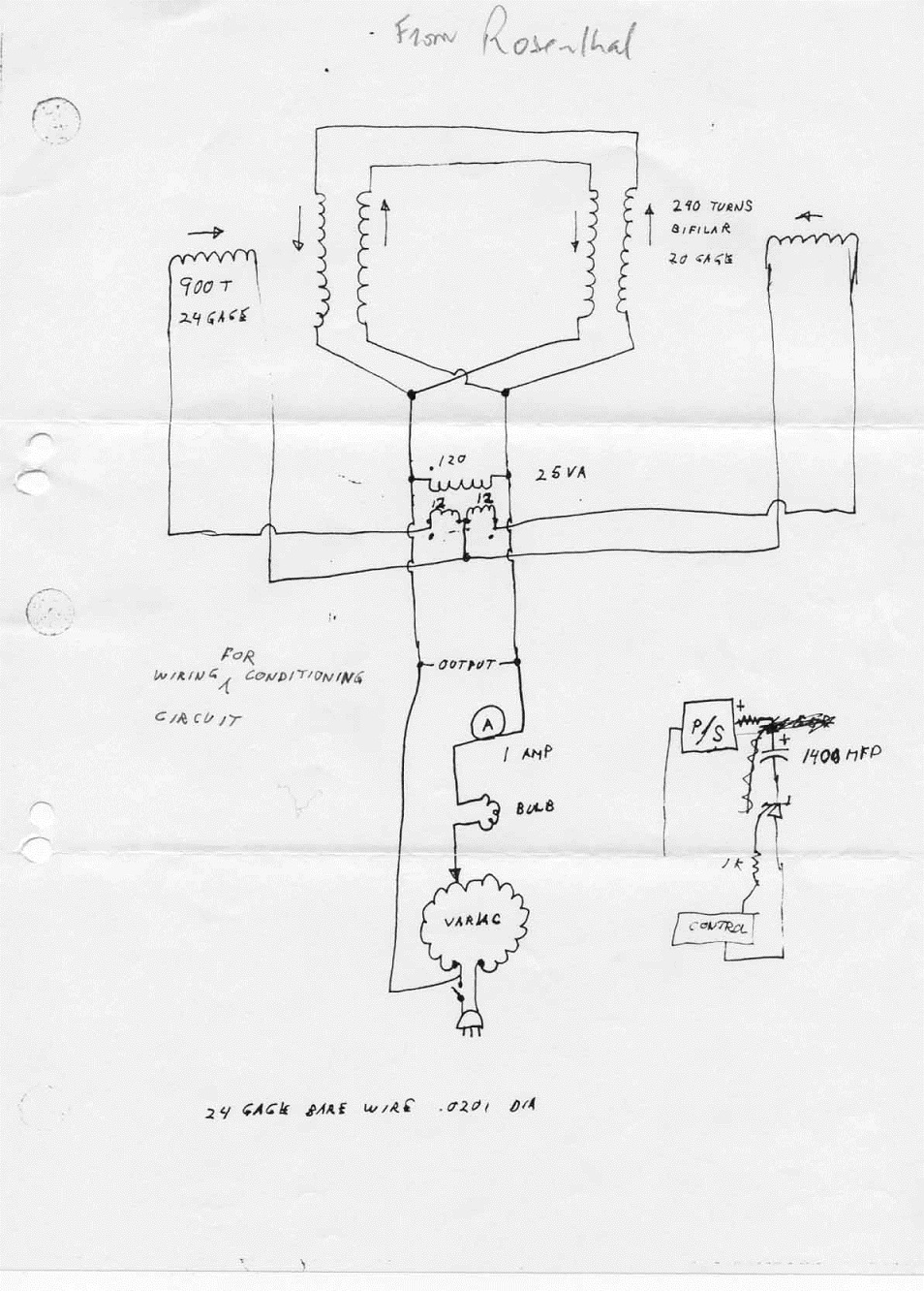
Showing the use of a varac in series with the light bulb load, and an uncompleted pulsing scheme on the right.
Label is to condition the magnets.

Showing the addition of FB1, FB2, as a feed back loop to eliminate the AC wall power iron core transformer.
The addition of T1, T2, to start up the system using a battery on a reversing switch.
The circuit between EX1 and FB1, EX2 and FB2 are the cross coupling between the two systems of 90 degree interaction.
Note the FB1 and FB2 coils are not canceling wound.
The T1 and T2 polarities are opposing fields.
The P1 and P2 are also opposing fields.
Back to PCC menu
