Hendershot Buzzer System - Fundamentals of Magnetic Field Vibration
Video from Over unity.com showing a successful buzzer system using Neo magnets. System output is 25 watts.
[Development Document 2020 - 2 - 29]
[Keeping in mind that many of these older systems were designed
using nothing more then machinist tools, a micrometer, a
compass, and parts taken from other devices that existed at that time.
The newer magnetic generators using Neo magnets likely will need an
O-scope to experiment with and quantify the resonance frequencies.]
1 - Angular Spin Cone off the Poles of a Magnet Vibrate
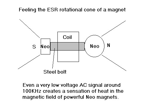 A coil is wound on an iron bolt, and any magnet can be stuck to either end.
Modulate the coil with a low voltage Frequency generator at about 100
Khz, and the spin cone off the other end of the magnet will start to
flex outwards then inwards over a small distance.
Sticking a hand in the cone, at approximately 45 degrees off the
magnetic pole, one can then detect this vibration and ensure it is
real. You can also change the frequency to one you are more sensitive
to.
If you drop the frequency down to below 10 hz or so, you may be able to
get a compass to vibrate a little in that area, if you are not
sensitive to feeling the field vibrate with your palm.
When we alter the strength of the magnetic flux, the cones will vibrate
with the change of magnetic field strength. Thus we can modulate the
field on a magnet, using very low energy levels.
Be aware however that higher frequencies have more energy. Magnetic
cones operate in the microwave frequency spectrum at Ghz frequencies, so normally we do not
feel or sense them until we modulate them with much lower frequencies.
Modulating a neo magnet on the end of a ferrite bar, has been shown to work in the above working Hendershot style URL video.
The unit produces 25 watts of power, from a small set of neo magnets positioned off the ends of the two ferrite rods.
It is not an over unity system, the magnets power the device and using neo's means they should last a very long time.
Neo magnets have an isotope bond, which supports the electron shell
magnetic field. They are the most powerful magnets we have access to
today.
It is likely the two ferrite bars oscillate out of phase across the
rear iron bar, and the coils set up an oscillating effect producing a
fluxuating magnetic field bouncing between them.
The coils are similar to the ones found in old style telephone ringer
boxes that Hendershot would have been using. They have lots of winds
and are high impudence coils.
They also have resonating capacitors across them in parallel.
2 - Magnetic Field Reversals Create Nodal Points at Specific Distance - Distance Tuning with Iron Medium
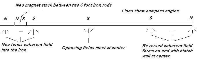 In this experiment, a long 60 inch threaded rod has a neo magnet stuck to
one end. A compass is used to now chart the polar effects moving down
the rod.
In this experiment, a long 60 inch threaded rod has a neo magnet stuck to
one end. A compass is used to now chart the polar effects moving down
the rod.
The magnetic field is discovered to reverse itself on specific distance down at the other end of the rod.
The distance between the last two nodes was measured then doubled, and
came out to about 44.25 inches, which is the natural, pole reversal
distance for the field traveling down this rod.
A 44.25" rod was then cut, and noted to vibrate up from the background
field. When a magnet was stuck to one end, the polar nodes came out
evenly spaced on about 22.125 inch reversals.
This is a scalar canceling trifield arrangement on the tunned iron
rod. It has three poles and can be flipped over by reversing the magnet.
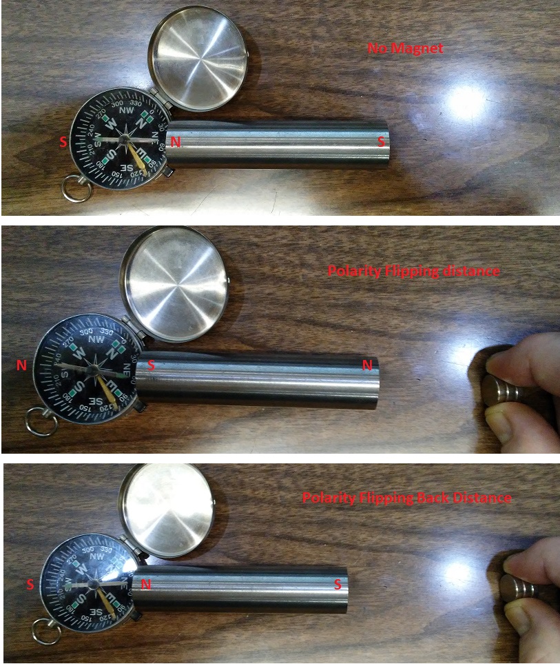
The important thing to note here is that if we change the distance
off the end of the magnet to the rod, there will be a distance out
where the field flips over on the rod, as air will not conduct the
field well at all.
This is the critical point of oscillation of the field where a
very tiny change of the magnets field strength will flip the poles of
the rod over, in theory.
In one distance mode the magnets field will take control in attracting
configuration, in the other mode it will came into repelling mode with
the bar.
In order to cause the bar to oscillate up with a magnetic field that is
reversing, we have to find this critical distance out, where the field
normally flips over.
Once this distance is correct a very tiny input to a coil on the magnet
should be able to flip the field over and produce an AC energy in a
larger coil wrapped on 1/2 the iron bar with far more mass available.
Two coils could be used on opposite sides of the bar and wired out of
phase so the EM fields would add as it flips over oppositely on each
end of the bar.
As the iron core flips over it's polarity, it will avalanche down the
rod
generating far more power then a small coil on the magnet that steers
it. The secondary effect will be out of phase lagging the primary
effect in real time.
Mechanical devices were connected that use that pulse of EM and move the magnet or the bar like a swinging arm.
While this effects seems apparent in some of the old mechanical devices
I have studied with slow moving long rods and levers, it may not be
effective at smaller dimensions, it is unknown but worthy of mention.
It is something a person from the past ages could have easily ciphered with nothing more then a compass and a measuring tool.
With these two experiments fully understood one can now begin to design
working magnetic flux oscillators, for which in the old devices we have
seen many examples of working systems in our history.
The mechanical ones seem very primitive, but they reveal an effect. If
Neo magnets can be used, they can likely run for a very long time
before loosing their magnetic charge, however we see from the distances
above this may not work for totally flipping the magnetic field over
rather oscillating the intensity of the magnetic field, without
flipping it over.
The magnets of olden times would
slowly wear out. Magnetic field drops as a function of distance cubed,
so it drops off pretty fast with distance, however with Neo magnets the
distances are increased tremendously as witnessed in the above photos.
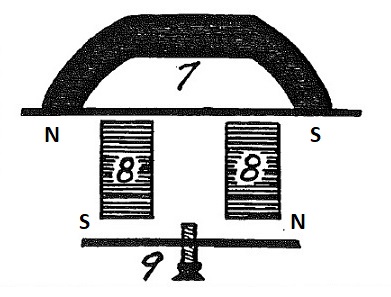
3- Hendershot Magnetic Field Effects - Flux Oscillations
In the Hendershot Mark 3 buzzer
units, this unit is used to generate the AC oscillations with no other
external energy applied we are aware of.
The unit consists of two operating field sections that interact between 3
magnetic fields, with the use of shunt bars operating between them at
the critical points of Field modulation in the two iron core coils.
It should be noted that the goal is to achieve a fluxuating or flipping magnetic field
in these two coils, in order to generate an inductive
AC voltage generator system in the copper coils.
Buzzer Coil Fields
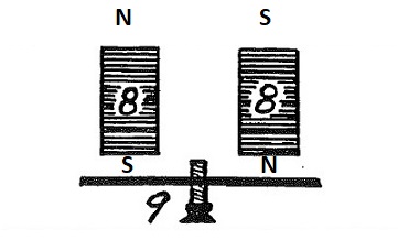
Noted that these two magnetic fields in the bottom section, will normally couple together as
shown above with reversed polar attraction
to one another. However
close we set the tuning bars, will determine the amount of coupling
between the coils in this attractive loop, but also the distance
between them comes into consideration. The magnetic attraction of the
loop will have a cone vibration frequency, which can be varied
with the tension of the field.
In some circuit diagram photos we have seen
where the two coils are shown to be wound in opposite ways and some in
the same way, such that an inductive kick from a changing field
intensity of one will
either weaken or strengthen the field on the opposite coil via the
coils wiring causing it to change also with the phase differential of a
copper coil or a 90 degree phase shift in each coil. Note simply there
are two ways to
configure the phase of
the wiring between the two coils in series. If both coils generate an
in phase
kick, the current will be amplified, if they oppose then a higher
vibration node may result as a scalar canceling effect as raw power of
physical pressure. Mechanical systems require much tweaking,
a 2 channel scope on the coils to see the phase differential and
amplitude may assist.
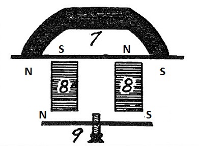
Note also the angle between the radar magnet that was used [7] and the
coils [8] may be a spin cone vibration effect found in these 45
degree angles, where it takes very little energy to cause the field to
shift angular vibration coupling.
In theory as we pull the two coils out from the upper bar, there may be
a point found where the magnetic field flips over on both coils and
produces an inductive kick. Both coils may reverse at this distance out.
This would be one of the critical locations where the field can be completely flipped with
very little energy sent through the coils as a reversed field. Move the
coils closer until they just flip back under the power of the magnet,
then determine how much energy it takes to flip them using a DC power
supply in opposition to the field. In another mode both coils can
be set up on opposite sides of the flipping point, if the distances are
close enough and they can cause each other to flip back and forth.
Lastly both coils may not actually flip polarity if the pulsing between
them on the copper wires goes out of phase, we could end up with
pulsating DC bouncing between them. In this case a magnet could be used
to start the field oscillating.
Showing an attraction loop of the field overpowering the thin upper bar
at the center, if in fact that is the effect. Other wise getting the
distance out further should also produce a flip in the coils, without
overpowering the upper bars field.
Hendershot used old telephone ringer coils with values to handle
60 to 100 vac normally at frequencies between 20 and 60 hz. These coils
have pretty small cores compared to the units we were experimenting
with in 2013 in the photos above.
The last time I had access to these old ringer boxes,
was in the 80's and they were used a lot back then. The coils were in
the Kilo ohm ranges and used very small wire with a great many turns on
a soft iron core about 1/4 inch diameter or less.
They were fitted also with a series capacitor around .47 mfd as I
recall. Today these have all been replaced with electronic ringers. I
was not able to obtain any of these coils at the time of our
experiments, so abandoned the project at that time.
It has also been noted that with
mass vibration effects a self sustaining vibration field can be
achieved between two elements that are set to vibrate at a pi/2 ratio.
If the two magnetic coils were set to a pi/2 ratio on frequency, it may
produce some interesting results. Results of pi/2 harmony state is
usually a sine wave output. A pi/2 field ratio will generate both a
square and a circle form field effect, connecting the quadrature EM
circular field to the platonic form square field that mass vibration
can couple to. To date this has not yet been attempted with EM coils,
but it works very nicely with mass vibration coils.
This document is a starting point
for development of the mechanical buzzer system we believe Hendershot
had developed with the simple tools he would have had access to in that
era, as well as an outlook for improvements shown to be working in the
current videos people today have achieved success with Neo magnets.
Dave L