Bashar Fractal Cones EMF Test 1
8 / 2 / 2014
Test Setup
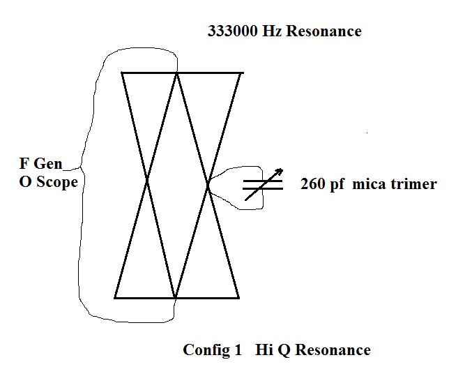
[Hi Q Resonance Configuration]
The two cones were wound in opposite directions on the wooden coil form.
While winding one cone the form was rotated CW, and on the other the form was rotated CCW.
The wire was added from the small end towards the large end.
In this configuration, with voltage fed from both ends, the two coils in parallel, the two magnetic fields will attract.
If they are instead fed in series from one end, the two magnetic fields
will repell and become a normal magnetic field as on a coil.
The smaller dual cones came out with an EM resonance at 365 kHz, and missed the target by 32 kHz.
I calculate they should have had approximately 11 more turns at the bottom end.
This can only be determined after the build, as the resonance
characteristics of this system are not predictible to any practical
degree, changing as the two cones are merged, likely due to mutual
capacitance.
There was also a strong EM harmonic resonance at 812 kHz and one at 1030 kHz,
which seem to defy logic for a resonant circuit, as these harmonics are
fractured and not "even or odd multiples" of the 365000 Hz fundamental.
It was discovered the wooden coil form is short by about 2 cm in height
and the diameter of the opened end of the coil is too wide for serious
T field vibration resonance.
Deutrium Resonance Cone Dimensions:
Height 511.18 mm
Diameter 302.84 mm
Side Length 533.13 mm
[ These are vibration resonance energies from the background field
and can be verified using SS caliper at 1/10 scale (2-19-2016) ]
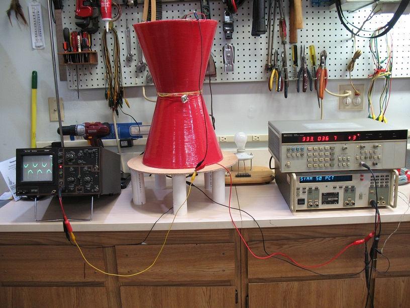
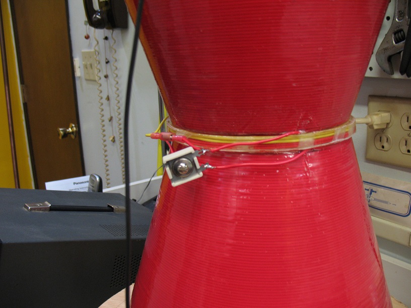
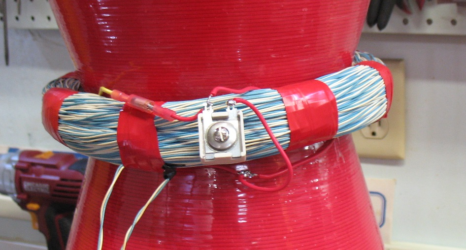
Shown in the photo below:
A 260 pf trimer capacitor is added, in this test, at the center,
running between the two cones electrically.
This adds capacitance to the center crossing point and drops the
resonant frequency to the 333 kHz range for perfect EM tweaking adjustment.
As the capacitor hits resonance, there is a drop in applied voltage at
the tips as the cone absorbs energy.
This energy aparently moves into the magnetic field at the center, which was verified later using a coil around the center area.
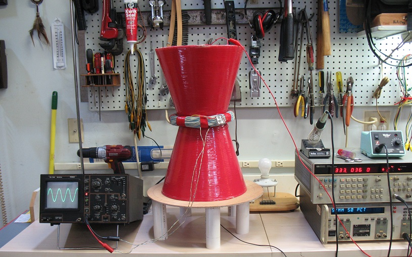
A photo of the test gear setup below.
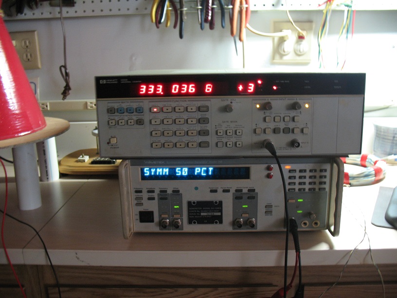
There is no equipment I have which can hold a perfectly stable 333000
Hz pulsing signal.
My analog unit drifts within about 100 Hz, and my digital unit
seen below warbles off frequency by about 1 Hz around a 36 Hz
offset of expected frequency.
The one pictured is about 36 Hz too high in frequency, as shown on the
very accurate HP frequency counter.
This is used to get the capacitor in the ball park.
The scope is connected off the upper and lower tip of the cones, along
with the function generator.
The capacitor was peaked using a sine wave for a dip in the voltage,
then a square wave was injected with 50 percent symmetry and the photo
below shows the result on the scope.
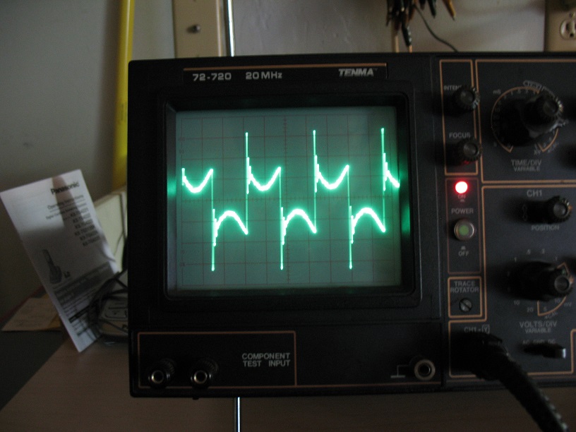
The sine wave resonance of the coils now appears upside down on the
tops of the square waves.
The result of winding the coils to magnetically attract, and also a
"center tunning" capacitor configuration.
Config 2 Center Loading Coil Added
A large center loading coil is added for capturing the magnetic field
at the point of highest concentration.
Scope is moved to monitor wave form on center coil.
Trimer capacitor is adjusted to peak the EMF energy.
Circuit Diagram Config 2
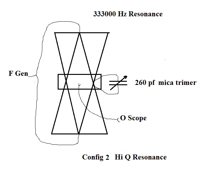
Tuning the 260 pf capacitor to resonance, now causes a peaking of
higher voltage on the center loading coil, as the voltage at the cones
tips off the F gen dips.
Our assumption was correct.
5v P to P input on the cones tips results in 12 volts P to P sine
wave on the center loading coil.
The dual cones first absorb the energy of the voltage applied to the
tips and then convert it to a magnetic field more highly concentrated
at the crossing point of the cones.
It is now a basic transformer circuit, which is resonating at 333 Khz.
Electric field is maximized at the tips and magnetic field at the
center.
Note:
With a "square wave" on the cones at this frequency, there is "headache
energy" to 20 feet out in all directions.
With a sine wave on the cones it is much easier to work around.
8 / 2 / 2014
Dave L
Back to PCC Menu
www.ResonantFractals.org