Joe Cell Applications - Radiant Light Model
After working with the cells for a time this was my first
experiments in attempting to understand how vibration fields are
involved in this, and if they can be adapted to increasing the
energy output of cells.
I was using human resonance fields in attempt to vibrate up the water
by cutting the tubes to specific length, not yet realizing, nearly any
frequency can be installed on a JC tube if there is another one present
to interact with it geometrically.
Most of these concepts were later perfected to target the vibration
resonance of the water H-O bond, and these old concepts were abandoned.
However the concept turned out to be accurate, vibration manipulation,
or radiant energy, is the main power source for the cells.
There are many inaccurate statements on this old document, but it shows the progression of learning by doing.
2020 - 4 - 17 Dave L
Updates
[Chart corrected for math errors 2 - 5 - 2008 DL Approx .002" off on 2F and below in old document]
[ Fractals added for clarity 1F,2F,3F,4F have been referenced separately]
[Introduced diamagnetic lengths for water and copper tubing feed]
[New comprehension of Tube delivery systems Length to Engine, and Shielding]
[Aluminum cone angle formula for new sample cell.]
[Diamagnetic response observed between SS rods for a 1/2x shift new section on Design]
Due to the recent work with the Radiant Light Rods this document is
organized to offer a model for design that may become useful to the designer of cells.
It was recognized early on that if one knows why they are doing
something, they can design intelligently. It is not our intent to limit
experiment in any way to any particular set of dimensions or any one of
the many possible gravity frequencies that may be available. Each
frequency may have different uses yet to be explored. Try some of the
lengths first and see how they interact with you personally before
proceeding to build a cell. Work is underway to identify more of the
light resonant lengths to assist and I have no doubt there are other
dimensions that will do many things.
Working with Torsion Systems
A torsion system can be thought of as a device to manipulate Radiant Light.
Since this light is already present within all matter and moving at c
velocity between all particles and atomic shells, there is already
ample energy within a system to power it. Our goal is to discover how
to resonate this radiant energy and how to turn it either to a divergent flow creating gravity, or into a convergent flow
which may very well create anti gravity, as has been reported in Joe
Cell technology. This was previously identified as inflow or outflow,
but can now be called by its rightful name, Gravity.
The Joe Cell is perfect for making this turn from the linear form
resonance to a circular form convergent resonance, directly down
shifting Light into power.
All the matter present in and
around a Joe Cell will either increase its spin energy, decrease its
spin energy, or become neutral to its spin energy, but no matter
present can be ignored, because the Light photons are doing this in all
matter. This includes every screw, every spacer, and every casing
around the cells, and how far they are setting from a resonant element.
Joe Cell Functionality
[As perceived at present]
Tubes
The tubes linear distance can
be thought of as lazar generating pulsing systems, and treated as such
will greatly enhance output. They are a direct model of the Light Rods.
If cut to correct lengths and perfectly flat on the ends will act as
mirrors to set up two flows inside that bounce between the ends. As
these flows cross through one another they will crash into one another
and generate divergent and convergent pulses at 90 degrees into the
water, both inwards and outwards along node positions
that form rings down the tube. The tubes will pulse the water with
energy. This is what has been sensed, and must be relayed to understand
the process.
If the circumference
of the
tubes is also resonant so that nodes of numbers evenly divisible into
24 land correctly then we will have resonance in two linear directions
at 90 degrees on these tubes and there may be a four fold gain
in output from this alone. This means circumference of 2x, 4x, 6x, and 8x
will give higher output then the other combinations. When rods are bent
into perfect circles the nodes will always move into a pattern or
6,12,or 24 at highest output. For only these combinations the same
nodes along the circumference will match the lengths nodes. [This is
the conversion to power of the radiant light, the circle setting up
convergence and divergence of the Radiant Light.]
SS tubes. Aluminum tubes are shown to have female spin off their sides
and male off their ends. Iron are the reverse of this. Stainless steel
is shown to have both, and for an offset of 1/2x we get a diamagnetic
pulsing off the sides as well between the two SS rods.
Water
The water is everything, it will receive the pulses and be altered in
torsion to spin along these radiant light pulse paths at 90 degrees of
the tubes. The water does not pulse but becomes constantly Radiant as a fully diamagnetic substance of constant pressure.
If the frequency is one you are not compatible with then headache will
proceed when the water is placed into the system. Don't despair you
have simply not found the right length to base your designs on yet, or
you have included combinations of odd stacking that do not balance fully but produce leaks in the torsion system radiating outwards.
If the water is also set to the same resonant length as the
tubes, and if the water nodes align with the tube nodes correctly we may have
another 4 fold gain of torsion to the system.
It
is evident that even numbered x stacks will be more effective for inflow and for
limiting any unwanted radiations from the cells. Water is set 1/2x lower then tubes.
Consider trying the water pitcher experiment with a single rod down the
middle to discover combinations for yourself, and check for headaches
and such things that may come up causing discomfort, irritability etc.. The rod I used is exactly 1/2" diameter and works great.
As the water comes up to torsion operating levels the rings of density can be sensed around the cell for outflow present.
If you succeed at reflecting all the light back inwards I would expect
the cell may begin to levitate at some point of charge and all
these out rings will disappear.
This is not known however from direct experiment, it may also gain
weight. The cell could also disappear if we achieve a total inflow of
all radiant light.
Tube Mounting
Obviously treating both the water and the tubes as pulsing lazar
generating devices, we realize that any matter appearing inside the
lengths of resonance will effect cell output. Joe seems to have come up
with the original solution by using spacers that are exactly the same
thickness as the cell spacing, set to the positions of a triangle.
Further if these are cut to the same exact length and positioned away
from nodes or on fractal positions of nodes they will begin to also
interact with their own internal Light, either strengthening or decreasing the resonance effect.
Cell spacing can be thought of as being a 2x node length for a
generating cell, approximately 1/2". The most desirable spacing for all
matter present. 2/8 x or 1/4 x for all pieces entering the water
anywhere. Round head screws are out as they will create a divergent
reflection. Their material type will not subdue this reflection,
but the screws themselves contain light energy also that will interact.
I have verified this by creating rods of wood plastic and other
materials, they all exhibit the same distances and fractal breakdown
with the Radiant light.
Casing
Anywhere there is a change of material, there will be a reflection and
a new resonance forming in the next layer of material. If you want to
set the cell into a plastic mounting enclosure, then spacing will
effect the cell as will thickness. If there is an air gap it should be
cell spacing, and never 1/2 cell spacing as this will act against the
torsion. The thickness of the plastic should approach cell spacing.
about 1/2" and never half this or 1/4". For custom designs of fully
resonant circumference then use these more accurate dimensions and not
the 1/2". These are found in the charts for a specific light resonant
frequency. Also below is found the method to determine the spin directions for distance from an active tube or water surface.
The casing is particularly specific radiant outwards of the water
cylinder and below it as well. Nothing should change thickness along
this up down line of material thickness, and mounting brackets would be
best outside both vertical line of water and horizontal line of water.
The casing should be at least examined for non resonant or negative
effects, even if it can not be made fully resonant at cell spacing.
Plastic touching the cell directly should be treated the same, use cell
spacing sizes and avoid exact 1/2 spacing sizes that may set up reversed resonance.
From a gravity standpoint the best casing for a total containment would
probably be an aluminum tube casing with correct spacing and thickness
to support the cells dominant spin system. The Aluminum being
diamagnetic would give the most anti gravity effect possible. As the
cell uses a mix of iron, chromium or SS, it is a mix and will tend to
both radiate and converge the Radiant Light until the voltages set
up the inflow. A properly spaced Al case would increase the inflow
effectively, and an improperly spaced one will pull a cell dead faster
then any other metal commonly in use.
Cell Dynamics
It was realized that the fields present in the Joe Cell geometry
determine which lengths to use where. The diamagnetic field sits at 90
degrees to the magnetic field. The isotope chain alignment of a tube is
vertical, so the magnetic lengths will be used vertically. The
diamagnetic field will be operating at 90 degrees to this all the way
around the tubes like wheel spokes, and so the diamagnetic
spacing is used along this line, moving outwards from center of the
cell. The final length, circumference, will be determined by the
combinations used. If the tube circumference also hits a sacred length
there may be more gains??? In a spherical system this would happen
naturally but in a concentric tube system there are many variables. A
general rule is to use Golden and Blue Light lengths for all the
vertical dimensions of everything including the water, and then use
diamagnetic lengths for spacing only along the center to outer radius
and diameter of the system. Now the proper fields will be resonating
along the correct planes of motion with respect to the Radiant Light.
Fractal Segmenting
[Chart corrected for math errors 2 - 5 - 2008 DL Approx .002" off on 2F and below in old document]
Blue line indicates a 2x of the 2F fractal length chart. [.47436"]
The energy radiant from a resonant rod divides itself into these 8
nodes evenly at very even spacing. Fractals are treated by their maximum length
of major nodes. As we cut a rod to 1/8 its length we see 8 new nodes appear. Before we
cut the rod these same 8 have very little energy present, after we cut
they have as much or more then the larger rod. From this chart can be
derived tables if desired to reflect only one Joe Cell light resonant
vertical system. First we divide the 15.1796 into 8 equal sections and fill the
upper table. For the lower chart we divide one area of the upper chart
now into its 8 equal lengths. This is the fractal nature of the Light
as it has been observed. This process can be continued to as small or
as large as we can manage in practice.
If we understand that a major node system is always present when we have moved above the 2x distance, then we can fathom how the torsion will align between nodes.
The major nodes will dominate and suck the energy out of the minor
nodes of smaller fractal in the same length rod. A rod of the
full upper length will suppress the minor nodes and a torsion will
manifest between the major nodes that outweighs the minor reversals of
spin. As we cut a rod off on its first node now 8 major nodes will
manifest at smaller fractal with full spin reversal on each one that is dominant.
If we align two ~15" rods and now slide them apart lengthwise by 1/4"
we will feel immediate dissonant torsion and have headache over time. If
we now slide them to 1/8 of there total length the interaction will
become fully harmonious and very pleasant. The 1/4" distance is once
again shown to be a bad effect.
If we select tube size from the 1F chart of 2x or 3x the nodes from
chart 2F will be suppressed greatly. If we select an 8x from the 2F
chart [1.89"] all 8 nodes will appear strongly. The 1x and 8x are in
this manner the same and represent the highest output overall for Light
photon Radiance. But torsion is another matter, and will group between
the major nodes with one major spin dominant.
Node spin reversals

Spin energy is additive. A 3x spin will add to become an unbalanced
spin of 1x and radiate outwards with 1/3 the energy of the spin present
to 100's of feet outside the cell. A 4x system will be self contained
along its length and should not be radiant outwards to great distance.
The tube spacing
should be set to an even spacing as well as all components appearing
within the complete light resonant system if possible, when completed.
Water can be dropped one node to sense and tune the cell for no
headache operation of all the parts. Use the chart
that fits the part to find the fractal spin total Then locate it in a
space of matching spin in the system. This is presently
only from observation of wires rods, tubes, and water heights.
Experiment with odd stacks
should also be considered to verify or refute these findings. A cell
built to all odd stacks may become interesting to say the least, and
more human interactive. My 3x water level is very radiant outwards, and
I love it! Become aware there is a big difference. My 1F-4x water height is hard to get into even at close range.
This principle has only to do with cell radiance and balance. Do not
confuse this principle with inflow or outflow. In the Joe cell system voltage polarity
will control this. We do not yet understand the total interaction of
odd lengths with voltage polarity and experiment is still underway. We
now have simply offered a map so experiment can proceed showing the
steps, and spin is identified in steps rather then having to shoot in
the dark as in past times. With respect to water level we do not know
the best. I can tell you that a 1/4" level set wrong can create a headache.
Circumferences
[Node shifting]
As we take a resonant rod and slowly bend it into a circle, it is not
understood why, however observed directly, there is now a shifting of
the natural nodes into exact multiples of 6, 12, or 24 around the
circle, and all the energy is now radiant along these nodes. Further it
is noted that by using the rod Length as a circumference we get now a
total resonant system responding to the same light frequency but
fully radiant now at 12 or even 24 evenly spaced places.
If the ring is kept opened at one point but touching or even
close to touching we get the nodes appearing at exact distances from
the cut and thus can now control where they will align along the wheel of 24 directions. This method used between tubes will further align the nodes.
If we now use a light resonant length of 2x, 4x, 6x, 8x, or 12x to
make this loop, the distance is maintained from rod spacing to
circumference spacing and nodes will not shift at all. It is not fully
understood how important this is, but a best guess indicates now along
the tubes, node spacing will form a square grid system
of tempic field. [The circle into the square, or squaring the circle.]
This method has been noticed in other systems as well. Now having a
fully balanced grid set up on the tubes of exactly square dimension we
should see equal compression from all direction into the cell, a
perfect balance of gravity generation to one center of gravity.
Cell Spacing
[The Diamagnetic Lengths]
Recent work indicates a very strong node in copper at ~1/2" in from
any end. Copper thus cut to ~1/2" interacts strongly with any of the
sacred lengths and this is also a diamagnetic node [actual distance is closer to 33/64" Closer examination of Lathem Lengths has shown this may even be closer to .52".
Here is a sample design showing an active element spacing that may be maximizing this effect for water nodes.
SS is the circle that gives form to the Radiant Light of the Water.
If the active tubes are set to a golden length and the case to a blue
length, or reversed, then a harmony of resonant energies will be
present and no headaches should arise for the cell even if odd stacks
happen to be present. The diamagnetic lengths, horizontally appearing, will create tremendous
power in the cell, and the case will offer a pulsed form of this raw
power, making it tolerable, or even pleasant. On inflow polarity of
voltage this should mostly turn inwards anyway. So we dimension the
water itself to set up the raw power field. Now if we dump the water out we loose the power effect and the
cell becomes a harmless radiant system of only healing Light energy of
the female aspect.
A Cell set up using Golden lengths in the vertical dimension and
diamagnetic lengths as the radius is showing promise. It is however
reported to go dead at nightime, and then recharge itself during the
day.
Peaks of low were reported by vertran cell experminters as 3AM and 2PM, and corresponding highs at 11AM and 8:30PM.
Centering

As a meditator I must mention that if all the Resonant Light lengths
are centered we get a much nicer feeling harmony, however this is not
necessary for transfer of energy between systems, only one node in each
system needs alignment to couple them all together. This would entail
extending the outer container downwards with another SS cylinder of the
same diameter as the case. Now all the energy is transfered between all
layers from a center position and we only need consider ways to get
alignment at the center. The following samples represent a few
compromises.
Design
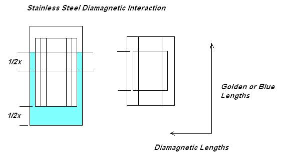
It was noted that two SS tubes set to 1/2x different heights create a pulsing diamagnetic repulsion.
Also that an Aluminum and SS rod offset by this amount creates a strong
torsion interaction. It is believed that doing this with the water will
increase cell
strength. As well it can be done with the tubes if there is ample
distance to play with. It was
also discovered that the lengths used must be diamagnetic lengths on
the cells horizontal spacing, but can be other frequencies in the
vertical alignment. This is one
quality not available with the spheres, which will be wrapped with only
one spacing and thus contain only one frequency. The picture on the
left shows the water height for tubes of 2x height. On the right is
shown a staggered tube spacing for a 1x 2x combination set staggered by
1/2x.
Now the tubes also repel one another, and not merely the water. [Effect not yet tested for staggared tubes.]
The water is now a 2x height exactly and so are the tubes, offset by 1/2x where diamagnetic interaction is maximized.
These are dimensions to be used along the horizontal of the cells that may aid operation for all diamagnetic materials present.
Cell spacing fractal choices:
Laythem Length fractal 1x - 8.34375" [8 - 11/32"] 1/2x = 4.171875" [4 - 11/16"]
Triangle inner leg -
1x- 2.3" [2 -
19/64"] 2x = 4.6" [4 - 19/32"]
Phi Length -
1x [ 166mm] [6 -
15/32"]
Base cell spacing - .52"
These lenghts are used for the vertical dimensions:
Tube heights, case heights, water heights:
Blue - 1x - 3.458" 2x - 6.9167" 3x - 10.375"
Gold - 1x - 1.8975" 2x -
3.795" 3x - 5.6925" 4x -
7.59"
One could simply take the tubes and drop them to the bottom then draw a
filling line inside the case. Now jack the tubes up to running height
about 1/2x of vertical node length.
Tube Spacers:
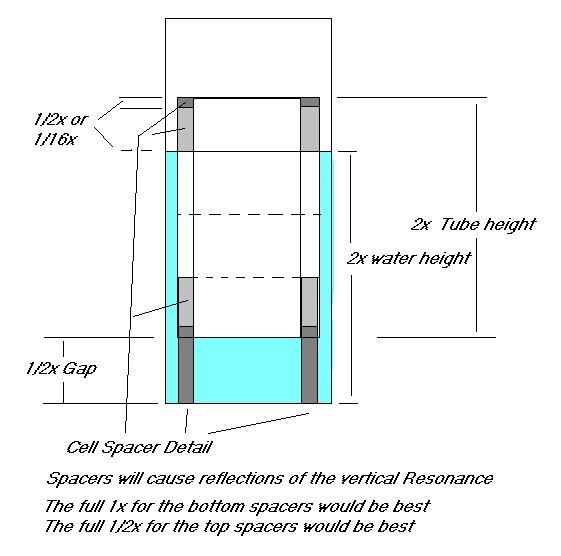
2 shades of grey shows some spacer options.
All spacers to be cut to a 1/2x or 1/8x fractal of the Golden or Blue Light
length chosen for the tubes, hopfully matching the tubes height off the
bottom. If they are cut as exact
wedges with curve inside and outside but straight sides then no curves
will be present to create divergent radiations. A spacer should
be a 1/2x length along its vertical dimension.
Golden Light spacer heights:
1x bottom spacer 1.89745"
1/2x top spacer 1.89 / 2 = .94875 = 61/64" ~ 15/16"
1/8x optional shorter spacer 1.89 / 8 = .2371875 = 15/64"
Notes:
It is also noted that the 1/2" measurement has been further refined as a strong diamagnetic node for copper lengths.
0.515625" - or - 33/64"
This is slightly bigger then 1/2"
It is unlikely we can locate stock SS down to the 64 of an inch for a
diameter but this increase will give another gain, I have no doubt..
-----------------------------------
In this first design of Light Resonant components we have ignored tube circumferences.
2" - 6.283185"
3.125" - 9.81747"
4.25" - 13.35176"
5.375" - 16.8886"
-------------------------------------
Cones and Tops
It is the main objective to transfer this torsion system to the engine. Can you already guess the best tube size?
The cones to transfer torsion most efficiently must align its angle
with one of the 24 angles of coupling for torsion systems. Since this
cone will cross all the cells at top we could consider the best angle
to intercept each one with correct reversed or 2F 2x multiples of spacing.
Generally any angle from 90 degrees to straight up, in steps of 15
degree increments will become a transfer system for the Light photons
to couple and shoot through. If the top of the case is also a 1F-2x
multiple of spacing distance off the top of the tubes then if we slant
at 45 degrees we hit over every tube at the same adding spin node
position. Figuring now the air as a secondary medium of transfer and
calculating its distance as a fractal. However we have also noted the
special angles of 30 and 60 degrees are more coherent to generating electric fields then the others.
Consider a 45 degree cone ending in a 1/2" tubing system. Now the
centers of the rings will hit the cone at a square root of node squared
distance along the cone??? Back to the fractal charts. A chart of
various cone angles should be made to consider these distances up the
cones and determine spin interaction. A flat lid at the correct
height may make this a bit simpler. An exact length of 1.89 from tubes
to cone top might even produce the blue glow???? Work needs to be done
in this area, but now you can see why.

Pictured is one section of the cone rising over the tubes of the cell below it.
An angle of 60 degrees rise will give a function of 1 2 3
for the triangle formed between tube spacing rise and cone length
within this segment? This would seem to create a 6x distance exactly
along the cone, a 2x along the cell spacing, and a 4x rise. This would
probably be the best angle, other then a perfect 90 at correct height.
These two look best right off. A 30 degree lid angle would also be additive as to spin.
As one begins to combine different resonant system, using one frequency
for water and another for the tubes angles, this will have to be
charted again. Distance between the tubes will be the waters lengths,
and distance above the tubes may be the tubes fractal lengths. One thing we must realize, there is no one perfect angle for all the possible Joe Cell designs.
For an Aluminum or Copper lid cone:
We work with the diamagnetic numbers now rather then the iron ones.
For the upper example, in cell spacing section we have a Run of
9/16" per 2x between all tubes, but along the cone we still want
a length of 33/64" if possible between 2x nodes because this material
is not broken up. 1 2 3 no longer works perfectly. The exact angle will
be the cosine of .5625 / (.515625 *3) I believe. This should be a
little less the 60 degrees if I got the formula right. The 6x side
needs to run further to compensate for the 1/16" tube widths. This
method will couple the waters convergent spin into the lid perfectly.
Delivery Tube
Tubing:
I think we can see that possibly copper tube may be the preferred method of coupling. Since this is copper it must be treated like a diamagnetic material.
The scope of trying to predict a node alignment in copper would be
impossible for me at this point. We can expect to see nodes of some
kind at almost every 1/2" with some missing, some turned inwards and
most turned outwards. Magnetic fields will shift the nodes compressing
them together, as we move along in space and encounter them. Copper
nodes are very reactive to the outside world. This is the downside to
Joe Cell functionality both at the water and the Copper level.
There are three approaches I see best for copper tube considerations and different reasons for trying each.
1/2" OD Copper Tubing - [Optic Propagation]
5/32" OD Copper Tubing or 1/8" ID - [Resonant Propagation]
Wire of a heavy gauge
1- For 1/2" an Aluminum shield
at 1-1/2" ID diameter would be the premium isolation for this
tube, but not very practical. The 1/2" spacing around the inner tube
would increase the energy as it propagates. This system would be very
hard to build and all angles would have to conform to the wheel of 24.
1/2" is based on a resonance in the air between the copper, treating
torsion as a wave in space.
2- Personally I would avoid the
1/4" tube sizes, and even favor 1/8" over that choice, not wanting to
experience a headache from dissonance. 1/4" size will encompass only
one side of spin, and drop the other. However if we take 1/2" as a
circumference .15915" is the diameter, and 1/8" .125 ID copper may come close with its thickness added. The ideal would be probably 5/32" OD copper tubing
if one could find such a thing. This is based on a copper circumference
offering resonance around it, and assuming that having a 90 degree
resonance will aid keeping the level higher as it propagates.
3- If we view the wire as a
Light Resonant system, torsion will be delivered from a node on one end
to a node on the other end. Wires of resonant length can couple to a
cell node and then an engine node can be set up as well.
Length to Engine:
As copper produces strong inflow nodes at 1/2" [33/64"] on either
end of any wire length that is resonant to Light, this may be a better
approach. Even bent into a coil with straight ends these nodes will
appear and are very reliable. If we simply cut the tube to an
exact Lathem or Phi Length multiple of 8x. There will be a strong 1/2"
node on both ends. The strong tempic field coherence of the resonant
length will couple the energy end to end and that is that. Stay with
smooth curves or sharp angles of the wheel of 24 [15 degree
increments.] Use the lengths for Water Height found
in the charts above and set up an even count end to end. Only use
one of the lengths they cannot be combined that I am aware. As the
entire length comes up to torsion at resonance it will
transfer torsion end to end without loss. It would be
interesting to try a simple wire for this as well, we have never made
this connection before! It should work extremely well. A few examples.
Diamagnetic
18.4"
51 - 3/4"
66 - 3/4"
147 - 1/2"
Iron - Electron
See above charts for heights.
At the end we work with the
last 1/2" or even 1" overlaying the blind plug, and then propagate from
there to the engine. The insulating material needs to be scanned for
nodes but will very probably be strong at the golden light distance, as
well as iron [engine] and air. If the tube is made resonant at one of
the iron lengths it will probably become a torsion propagation element
also.
Joint:
Where the tube joins the cell, we want the node setting at .515625"
[~1/2"] to hit the cones top point of crossing, or we want it to hit
the common node of the cell down inside the water at bottom center.
A hypothetical cell having say 6" long tubes, with a water gap at the
bottom of 33/64" will set the waters strongest coupling node to the
bottom of the tubes. If we stick the tube all the way to the bottom now
its node will align at the same place and sould couple just fine. This
cell if filled to the top of the tubes will come out very close to a
phi length of 6.5354366" and this cell should be quite strong for water
depth also. If the tubes are instead made to 6.0198116" it would hit
exactly at the top also. While the tubes do not seem to be Light
resonant, the water is and this will create a strong cell at the power
level, with probably little higher pulsing of golden or blue light.
Engine coupling of Torsion
I wanted to offer a possible alternate method that could be tested.
Where the end section node of a copper wire of Light resonant length is
brought to the engine, An iron transfer system could be used having a
carefully spaced node where the wire is inserted to 33/64" deep. The
iron would wrap this at exact 33/64" distance around it and then attach
directly to the engine. This would maintain a direct physical coupling.
Rubber heat resistant hose or a rubber flask stopper could make up the difference, with all the
correct dimensions to fill the gaps and fit snuggly. Whatever the
diameter of the feed copper we then work outwards to design the plug
system. Having the iron completely wrap the tube will transfer torsion
from the entire wheel of 24, and the Radiant Light should flow better
to the engine block.
Shielding:
We now see why Joe cell is flaky as to outside EM. The diamagnetic materials all shift their nodes. When
EM hits the water or the copper transfer tube all the nodes compress
and alter distances, shifting the torsion fields off design alignment
and killing water spin resonance. Shielding will rely on keeping EM out without
using magnetic materials!
To minimize this we may try to set up two diamagnetic fields to work against one another.
Aluminum shields with 1/2" inch spacing. No iron can be used as this
will draw off the torsion and it will never reach the engine, Faraday
cages are out. The outer layer will cancel the EM because that is what
induction does!
The superior method, a scalar coil
wrapped over the tubes will cancel EM and convert it directly to
torsion which may help or hinder things. A mobius wind would be messy
as to headaches, so an even wound Smith or weave might work best, or
simply a bifillar wired to cancel EM. Place a rubber hose over the
tubbing and try to get a full 1/8" or 1/2" thickness to raise the coil
off the transmission tube. Wind the coil over it and before you fire up
the system short the ends of this coil. After shutdown open them. This
places two coils wound opposing directions over the transfer tubing
that will cancel EM from outside trying to enter the system. This would
probably take hours to wind, but hey, if you want your car to go under
power lines then have at it.
A similar coil could be placed around the whole cell for shielding, but
remember a proper gap is necessary to maintain 1/2" cell spacing.
This sort of system will take the interfering EM and convert it to
usable torsion energy, and this may actually increase the cells
functionality rather then decrease it. This is putting the EM back
together into a Radiant Light energy.
As a cheap alternate two layers of Aluminum
shorted at the wheel of 24 positions around them, or with a seperate
switch at one point, and spaced 1/8" or 1/2" apart may also tend to
cancel EM entering the cell. One must use two diamagnetic materials
hitting one another in cancelling form. If the EM gets to the SS then
we are lost and all water nodes will start to shift and break up spin
allignment! Use caution on this so as to avoid a resonant height as
there will be no way to shut it off! With the water we can alter the
level or dump it out. With a solid Al structure there is no way short
of cutting it up if it starts to resonate Radiant Light energy.
Charging Power Supply:

By careful alignment of the cell charging delivery wire one can charge the cell with both E field and T field.
The node that appears on the wire from the scalar coil can be used to
align the cell, as well deliver a torsion force to the cell as the
voltage sets up the water alignment. It should be placed on the tubes
seam line. If correct distances are found this may greatly enhance cell
charging rates, especially for high loss cells that were not made light
resonant. The torsion field of a scalar coil will propagate out with
the electrons direction of travel down the wires. From the scalar
bismuth coil to the cell must be an exact light resonant length of some
form. The return positive wire can have a normal iron core filter. This
will stop the torsion from reaching the power supply and also filter
the AC ripple off the charging DC voltage hitting the cell.To make
these scalar cancelling coils a bifillar wind is fine, current must
flow both direction in adjecent wires on the form. No filter capacitor
is used as this would alter the dynamics of this charging system using
both AC ripple and DC input to create the voltage and torsion to charge
the cell.
Blue Light Lengths
From the info received in
meditation it seems apparent that a fully functional buoyant anti
gravity system would use all three of the lengths in some way, to
achieve full stability.
The Blue chart appears to be different in that, its length of 20.75" there are only six segments
for fractal division rather then 8. This gives approximately 3.4583"
segments on the 2F chart with six divisions on all charts. Charts may
be laid out as above to experiment with this system as well. I have
been getting very good effects from combining the two systems thus far
with the rods and no headaches even though very strong fields are
present. They blend to produce a sense of spin, or rolling. If we then
add the diamagnetic form distances at some point, we could expect a
very strong power added to the inner of the system somewhere. Caution
is indicated whenever moving to the diamagnetic chart in the matrix
document, as it is the strongest of all the sensed length to date. One
dissonant length in the the system will then create total torsion havoc!
Spiritual Context
Many of the cell builders are having conversations with their cells and
communicating at many levels with them already. This section is to
relate what I have personally observed for myself in their use. Observe
yourself and seek the answers within you, not from others. Compare
notes with others, but experience for yourself if a thing is workable.
If it is not working for you , then do it different. Something no
scientist wants to face but is the nature of the conscious energy. If
you have no faith that there is Light energy within matter of
sufficient power levels to accomplish work, go to the physics section
of the university web sites on Quantum physics and start to read it.
Pay close attention to how photons propagate and how energy is
exchanged. Now study the nature of Voltage and how it moves at c
velocity and note the differences. Consider Tom Beardens work on vacuum energy and the E vector
potential.
While in physics they will describe Light as an Electromagnetic form,
at the same time you will discover that magnetic fields do not bend
light, only gravity bends light. Radiant Light is the propagation medium of Gravity. E
and B fields are the propagation medium of Electromagnetic forces and
these are not Radiant. The force
they have missed to define, Spin! It is carried within the Radiant
Light. In the spiritual arena there are a multitude of references to
the "Light" and even the "Radiant Light" from nearly every path I am
aware. I believe we will see the crossing of these two into one new
awareness of the Light itself and how it powers all things. Using this
power it becomes nearly impossible not to have these kind of
experiences, nothing less then Spiritual revelations.
As these cells open and start to power up altering gravity, you may
also experience emotional development. Much courage and drive if
present will allow one to master this at each blockage, if we become
aware and expect it. Scalar devices have long been recognized to have
this effect on humans and no one to date I am aware has offered
explanation as to why, before Kosol Ouch stepped in and started
suggesting we look for the Spiritual reasons. Observe yourself and seek
emotional assistance if needed. I cannot count the number of torsion
systems I have destroyed to regain a balance in my life and try to
comprehend this in operation. This is proof enough for me they contain
power.
All the knowledge presented in this document is direct result of influences of
Kosol Ouch and Kosol Open forum yahoo groups and the Guardians of Light, where it started. It is
freely shared, and Kosol is one of the only men I have personally worked
with willing to operate in this mode publicly, through failures and
successes, without concern as to how others perceive him. Whether he is
considered sane or insane is how one reacts to
having the light pushed directly into your face for a close look at
yourself and how you react to others. The conscious devices will
accelerate these reactions and often become a mirror to our own souls.
There were almost no other Spiritual seekers I am aware working openly
with energy devices, most will take a back seat and wait for the ones
that finally work, or simply work in secret. I have relied on Kosol for
the right push at the right time and always listen for the information
when he calls up. It is often where I will need to be looking at the
next step.There are now many others coming into the opened as well, as
the public perception has slowly changed towards the Spiritual nature
of science. More education is necessary to bring the mass population up to speed with over unity devices.
Most all the information
presented was a combined effort by members
that were connected on the Kosol Groups. The rod spin reversals and
node existence, were detected, modeled, and or confirmed from Alaska,
Canada,
Germany, Australia, and worldwide support team at c_s_s_p and
Kosol forums. Interaction were not always consistent for everyone, but
are progressing. We all perceive a piece of the big picture.
The first lengths were observed by Lyle Lathem to which we owe a debt of gratitude for openly sharing this knowledge.
The Blue and Golden lengths were observed by myself just recently, I have no knowledge if others have found these also.
Joe cells were observed by Peter Stevens I believe, and presented publically by Joe.
I wish all the best for all experimenters with this new form of energy.
Kosol has requested we observe this technology is from the Light, manifesting to him by the Guardians.
I also recognize this is where credit needs to be given. It is Light technology.
For me never has the work more directly pointed to this then now.
David Lowrance
c_s_s_p group
Kosol Groups
Home