AC Power and Torsion in Copper Wire
Personal notes, from April 2009. Dave L
A large spherical CU [Consciousness Unit] field raised from a [Lamp
Dimmer- Autotransformer] set up, and seemed to be connected into the
house wiring and the bench set up.
CU was approx 10 foot in diameter around the area. Felt to be a self
sustaining Neutron type of field, holding charged spherical layers
around it.
100 watt light was powered with the input power switch in the off position. Light emitted had a
feeling of purity and was very captivating to the focus.
Autotransformer wiring was traced to reveal it opens both sides of the circuit from the
house but the case is still grounded to the output side of the unit on
its neutral side.
This allows the case to act as an A field receiver around the toroidal
winding.
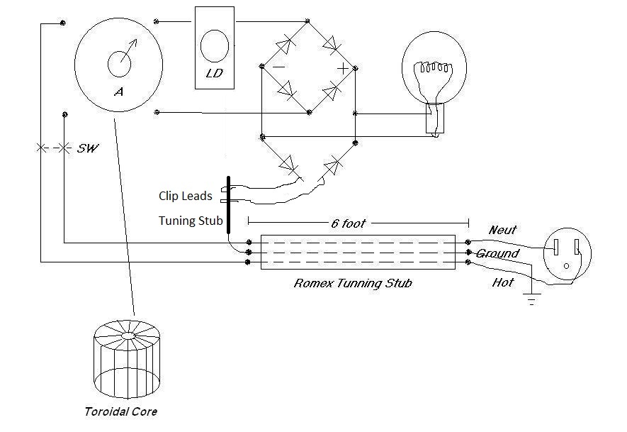
Diagramming the house wiring layout and the experimental components.
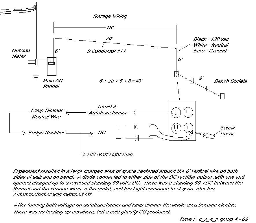
A large spherical field rose around the area approximately 10 foot
radius having an electric feel to it. Hair on arms stood up. Meter read
60 vdc across diodes touched on the + or - of the rectifier bridge.
There was also a 60vdc appearing on screw drivers anywhere near the
experiment with other meter lead to the ground wire.
Center of the field was cold, and after shut down took a week for the
area to dissipate the spacial charge.
Purpose of the two extra diodes back to the ground wire, is to
experiment with the torsion produced from a pulsed DC, and yet not have
much voltage present. Diodes were used separated with clip leads
running to various copper tube for tunning and crossing the two fields
at different distances. Finally a long thin screw driver was inserted
in the AC wall socket ground prong. The two diodes were mixed back into
the ground. That was when the large torsion field came up and the
system continued to power the bulb after power switch was turned off.
The field disrupted power in the house, and caused computer screens to
go into strange patterns. I was asked not to do it again! LOL!
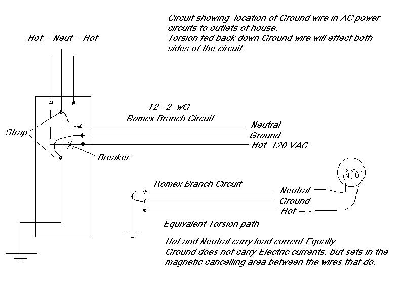
House wiring Breaker panel
8.129 inch Fractal off 60 Hz power grid
Notes I wrote after the Experience
Estimating Numbers:
On the reversed diode power supply a Torsion field resonance of the
copper wire was discovered about 8" as I recall for the components I
was using. [This may vary with the type of lamp dimmer but I do not
believe it will, I believe this is the shock resonance of copper
medium.]
8" x 9 = 6 feet
[The section of the system that went into a radiant energy mode, is a
multiple of 9 times the resonant length around 8" measured earlier.]
6' x 7 = 42'
Approximate distance of wire to panel, odd harmonic [7] of the 9x
vibrational field?
This leads to the possible design of a scalar canceling stub.
1 - Torsion field is the result of drawing current into a load, at
resonance all cancel internally, under power all cancel on the romex
2 - Take the torsion field out from the circuit and drive it back along
the stub in reversed direction without the voltage present to extend
the unbalanced condition and work the wire medium harder
------------------------------------
Observations:
We must realize that in an AC circuit with copper wire it is the wire
connected to the load that actually powers the load, and not the
generator. Electrons simply do not travel the length of the wire, only
the E vector voltage can travel along the wire at c velocities and it
delivers the power. Current then happens at every point where E field
is not the same along it, a side effect of the true power source which
is the voltage differential.
On a normal AC circuit positive and negative cycles must have different
torsion fields. The balance of Electron spin to proton spin is altered,
thus an AC circuit is really not balanced when loaded, even though its
voltage are being driven both directions in the same romex wire length.
The load splits the torsion fields some small amount. The atoms of
copper pull back to balance and this drives the load. The atoms have a
natural sine wave or torsion spin. This is the true reason wire must be
made larger to drive a higher current load, the wire is the source of
the driving power, as the load generally eats current to operate.
Magnetic fields in motors follow the current and not the voltage, and
moving electrons in the bulb filament create the light.
There are two types of torsion fields in an AC circuit. One originates
in the tilt angle of the Electron magnetic field hitting 90 degrees to
the wire, the other originates with the tilt of the nuclear mass
positive voltage vector hitting 0 degrees to the wire. Under load these
two angles split. There are two spheres with magnetic fields, and a
tilt angle between them, they spin opposing directions and thus tilt
opposing directions when loaded. The power of the circuit is the atomic
power pulling them back into alignment. Back to internal resonance at
the atomic level, in copper having a coherent torsion field end to end
without loss.
The lamp dimmer adjusts the velocity of the split, under load
condition. A sharp pulse under load.
The AC circuit draws both of these in both directions on 2 of the 3
conductors of the romex feed.
We now feed back only the torsion without the voltage along the third
wire for both pos and neg cycles of the wave, this will unbalance the
cancellation along the twin lead and make it so the system cannot
balance, or instead tries to balance into a different zero point level.
The wire will now work to balance and power the load in the process,
driving the nuclear side more positive on one cycle and more negative
on the other.
This is like a bunch of springs, with a power tilt angle of 30 to 45
degrees??? And a zero point at 0 and 90 degrees.
At 30 to 60 degrees is where we back feed some torsion to delay the
process and draw excess energy???
Max power lies at 45 degrees where voltage and current cross. If either
voltage or current is 0 there is no power in the load. Only where both
are present will there be power into the load. This flow can be powered
by Electron shell going more neg, or by proton shell going more
positive[OU], or by electron shell going more positive as with normal
EM.
------------------------------------------------------
My belief is that if one was to disconnect the power source from the
wall at an angle of say 45 degrees in the 60hz wave, the rest of the
power cycle would still be delivered to the load by the copper wire
that remains connected to it, and this would continue to be a sine
wave, as long as there is enough copper mass present to drive the load.
Sine wave originates in the copper medium, and is a characteristic of
it. The natural torsion wavelength must have an 8" fractal as well as a
44.5 foot one. This also explains where the 8" JC tubes are probably
really tapping power from, the power grid, and why they vary with
daylight hours of AC load on the grid.
Now with only this remaining 1/4 cycle of energy, we route only the
torsion field back down the tunning stub on the third wire to see if we
can make the copper over compensate enough to drive the next reverse
polarity side of the cycle.
Resonance is not on the EM side, but on the torsion field side. 8" -
44.5' resonant reflections, where there is no loss of energy in any
metals. The torsion energy in the wire does not dissipate in the load,
only the EM dissipates in the load. EM current is a secondary effect.
Copper mass resonance, must power the EM side, and the Electrons still
shoot through the load and are dampened or terminated.
This is quite simple when you add up all the qualities of torsion
fields, and connect them at 90 degrees to the EM fields. This must be
simple!
If I set up a piece of romex of 6 feet long, and then tune it to create
a standing torsion resonance with the load on the same end as the lamp
dimmer and diode bridge, then back feed both reverse diodes, may be
able to disconnect the power and have it keep running. Adjustment on
the torsion side can be adding more diodes in series, or a tunned 8"
stub for coupling.
You can see why there would be two cold fields created on each side of
the romex, the ground wire runs down the center. Only way to roll this
up without causing a cancellation is a pancake coil, so the two cold
fields can stay radiant above and below it without crossing anything
else. If a second coil is needed then an 8" spacing for an in phase
effect. It would appear that moving towards a stack of correctly spaced
pancake coils or even 6 foot circumference loops, should achieve what
we have been searching for. The more copper mass the more power output
can be drawn from a standing CU.
Downside is until you reach a platonic form there may be torsion sheers
created, but if the energy moves into the EM fields instead this may be
very small. Instead voltages will appear in the air above and below the
pancakes. These Fields can charge up diodes like they were batteries.
Note my distances come out different then in the TPU system using only
the hot energy side.
Much experiment may be necessary to hone these correct geometric
distances, and copper wire mass lengths, but I believe the solution
will come out to be very simple in the end, once a clear picture is
formed of why each component is needed, and a standing CU can be
accomplished.
Dave L
Some basic duplication efforts to remove the field from the house
wiring
Experimental setup for pulsing and sensing the torsion fields in
Romex wire medium.
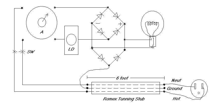
Note: Ground wire is not
connected at outlet. The Ground wire in the romex is for introducing
torsion imbalance.
I have theorized the ground wire needs to be connected outside to a
good earth ground, off the power grid.
8.129" x 9 = 73.161" /12 = 6.09675 feet
6 feet 1.161 inches
A 12x fractal of this appears at 6.09675 inches also and very near the
RA fractal location
A - Autotransformer
LD - Lamp Dimmer
SW - DPST Power Switch
Load - Lamp 60 to 100 watt light bulb
Diodes - Fast switching 3 amp 400volt
Tunning Stub - 6 foot Romex house wire 12 / 2 / WG [3 conductors]
White - Neutral
Black - Hot
Bare - Ground
Condition Where Wire Becomes Radiant
There are adjustments for the LD and A that will cause the 6 foot wires
to become powerfully Radiant.
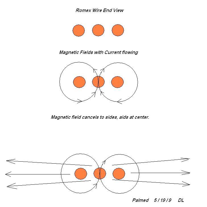
As AC passes through the wire the outer two conductors carry the
current in opposing directions. Each one will have a wrapping magnetic
field at 60 Hz that is 90 degrees to current flow. At the center
position between them the magnetic field
will be a magnetic field 90 degrees to the wire. Through this magnetic
area the third wire
passes. The power supply has two reversed diodes that will pass torsion
without passing electric currents, this is fed back into the
center
conductor of the wire.
The third or center wire will drive the radiant field on the Romex when
a load is present, creating an imbalance in the zero point of the
system.
Raising a Large Torsion Field
The basic circuit shown above, autotransformer is noted to have a
toroidal wind with case grounded on the Lamp Dimmer side.
You can see from this diagram that with SW in the off position, for the
light to stay lit, the circuit components are only acting to the earths
ground, a one wire circuit.
Duplication should use a ground wire outside the house wiring next
time, to avoid in house electric issues.
Levitation Site